semi合集-English.pdf - 第1900页
SEMI E54.1-1000 © SEMI 1996, 2000 6 Table 2 Dev ice Objects a nd Identifiers Object Na me Ob ject Iden tifier (tag) Su pport Required in a Device Comment Sensor/A ctuator/Co ntroller SacI0* Yes Only one insta nce per dev…
SEMI E54.1-1000 © SEMI 1996, 20005
6.4.2.1 Service Message Definition — There is a table
showing the parameter detail for each service in which
parameters are explicitly specified. The column
headings for the service detail are as follows:
Parameter Req/Ind Rsp/Cnf Description
Parameter X (see below) (see below) A description of the
service.
The columns labeled Req/Ind and Rsp/Cnf link the
parameters to the direction of the message. The mes-
sage sent by the initiator is called the “Request” (Req).
The receiver terms the message the “Indication” (Ind).
The receiver may then send a “Response” (Rsp), which
the original sender terms the “Confirmation” (Cnf).
The request (Req/Ind) and response (Rsp/Cnf) entries
can take on the following values:
“M” Mandatory parameter — Must be given a
valid value.
“C” Conditional parameter — May be defined in
some circumstances and undefined in others.
Whether a value is given may be completely optional
or may depend on the value of another parameter.
“U” User-defined parameter
“-” The parameter is not used.
“=” The entries M and C in the response can be
modified with (=) to indicate that the value in the
response must match the request.
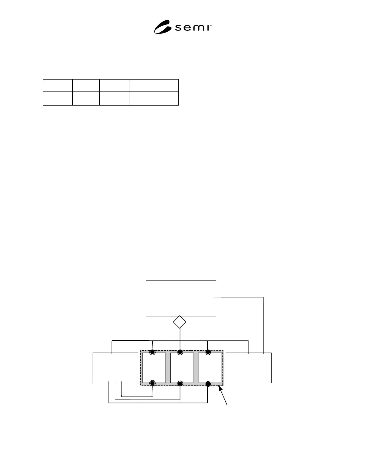
7 Device High Level Structu re
The high level object view of a device aggregation is
shown in Figure 3. A device is depicted as consisting of
a sensor/actuator/controller (SAC) object, a device
manager (DM) object, and at least one active element
object (i.e., sensor or actuator or controller object).
Each of these objects by definition has attributes,
services, and behavior. Note that the “Device” object is
depicted in Figure 3 only for purposes of illustrating a
high level view of the device and its component
objects; in the context of this document, the “Device”
object is not addressable, does not have addressable
attributes or accessible services, and has no behavior
defined.
This document defines in detail only the DM object.
The SAC, Sensor, Actuator, and Controller objects are
defined here only in terms of characteristics common to
all devices. A complete definition of a SAC object in-
cludes an appropriate sensor/actuator network specific
device model. This companion model could also com-
plete the definition of sensor, actuator, and controller
objects as appropriate to specify a device model.
7.1 General Requirements — Objects are defined in
terms of their object name and instance identifier.
Identifiers for all objects described in this document are
summarized in Table 2. Note that these identifiers may
be used for remote interrogation of an object instance
via the sensor/actuator network (see appropriate
sensor/actuator communications specification). Also
note that, in Table 2, many of the objects specified in
this document have exactly one instantiation per device.
De vice M an a
g
er
Ob
j
ect
(
DM
)
De v ice
Sens or
/
Actuator
/
Controller Ob
j
ect
(
SAC
)
Sensor
Ob
j
ect
(
s
)
A
ctuator
Ob
j
ect
(
s
)
Controller
Ob
j
ect
(
s
)
Coord
i
na
t
es
I
s
M
anaged By
m+n+p•1
mnp
mnp
(
A
g
g
re
g
ation
)
Act iv e Element
Figure 3
High Level Object View of a Device
SEMI E54.1-1000 © SEMI 1996, 2000 6
Table 2 Device Objects and Identifiers
Object Name Object Identifier (tag) Support Required
in a Device
Comment
Sensor/Actuator/Controller SacI0* Yes Only one instance per device allowed.
Sensor SenIn** No Zero or more instances per device allowed.***
Actuator ActIn** No Zero or more instances per device allowed.***
Controller CntIn** No Zero or more instances per device allowed.***
Device Manager DmI0* Yes Only one instance per device allowed.
* Only one object instance per device; identifier uses “I0” to specify “instance zero.”
** “In” is used to indicate the instance number of the object; “n” is a non-negative integer.
*** The specification of the number of sensor, actuator, and/or controller object instances allowed per device may be further constrained by the
appropriate sensor/actuator network specification.
The objects described in this document collectively define a device’s capabilities, including how it has been
configured for network interoperability. The information in the attributes of these object instances must be
accessible over the network and stored at the device.
Character strings described in this document have a prescribed maximum length. If the contents of the string are
shorter than the prescribed length, the string must be terminated with the null character: a byte whose value is 00h.
Note that this specification of null termination does not indicate that a sensor/actuator network protocol
implementation communicating a character string over a network must send the null termination; the presentation of
character string data over a network is sensor/actuator network communication protocol-specific.
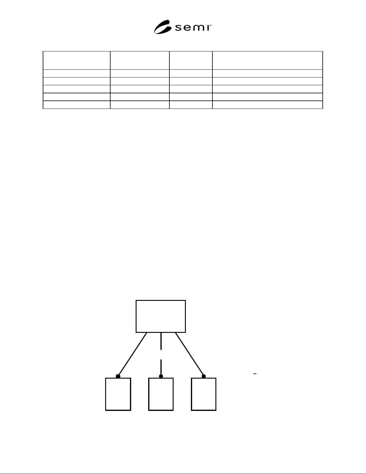
7.2 Sensor/Actuator/Controller (SAC) Object — The SAC object is the device component responsible for
coordinating the interaction of the device with the sensory/actuation/control environment. A view of the SAC object
is shown in Figure 4. The SAC object coordinates operation of one or more sensor, actuator, and/or control object
instances that collectively form the sensory/actuation/control portion of the device, so as to enable desired device
behavior. For example, it could coordinate the operation of the device sensor, actuator, and/or control elements to
enable device level data reporting or actuation, alarming detection and servicing, status reporting, device self-
testing, device shutdown, etc. The number of sensor, actuator, and/or controller object instances allowed per device
may be specified by the appropriate sensor/actuator network specific device model. An operating device shall
contain exactly one instance of a SAC object.
The SAC object has embedded in it other objects that address specific tasks associated with coordinating the
interaction of the device with the sensor/actuation/control environment. These objects are listed in Table 3. Note that
although only one instance of the SAC object is allowed per device, a device can have multiple instances of
embedded objects. These objects are described in Section 7.2.4.
m + n + p > 1
Sensor / Actuator /
Controller Object
(SAC)
S
m
A
n
C
p
Sensor
Object(s)
Actuator
Object(s)
Coordinates
Controller
Object(s)
mn p
Figure 4
Detailed View of the Sensor/Actuator/Controller Object
SEMI E54.1-1000 © SEMI 1996, 20007
Table 3 Objects Embedded in SAC Object and Identifiers
Object Name Object Identifier (tag) Support Required in a
Device
Comment
Assembly AsmIn* No Zero or more instances per device allowed.**
Local Link LnkIn* No Zero or more instances per device allowed.**
* “In” is used to indicate the instance number of the object; “n” is a non-negative integer.
** The specification of the number of Assembly or Local Link object instances allowed per device may be further constrained by the appropriate
sensor/actuator network specification.
7.2.1 SAC Object Attributes — All required and “common optional” SAC object attributes are listed in Table 4.
Note that many of the attributes are in text “human-readable” forms. Information provided in this table includes, for
each attribute: (1) an attribute identifier tag; (2) an indication of user access (via the network) to the attribute, (i.e.,
an indication of whether the attribute is network-settable); and (3) an attribute type. Required attributes must be
supported in all SAC object instantiations. Optional attributes may or may not be supported; a further specification
of the requirement of support for these optional attributes can be found in Section 7.2.3 and in an appropriate
sensor/actuator network specific device model specification.
Table 4 SAC Object Attributes
Attribute Name Attribute
Identifier
Access
Network
Required Form
Last Calibration Date SacA1 RW No date
Next Calibration Date SacA2 RW No date
Expiration Timer SacA3 RW No signed integer
Expiration Warning Enable SacA4 RW No* Boolean
Run Hours SacA5 R No unsigned integer
Reserved SacA7-SacA64 — — Reserved for future expansion.
* The Expiration Warning Enable attribute is required if the Expiration Timer attribute is supported.
7.2.1.1 Last Calibration Date (Optional) — An attribute which identifies the date the device was last calibrated.
The attribute is formatted as a date defined in Section 5.2.
7.2.1.2 Next Calibration Date (Optional) — An attribute which identifies the date the device is scheduled for the
next calibration. The attribute is formatted as a date defined in Section 5.2.
7.2.1.3 Expiration Timer (Optional) — An attribute which identifies the number of run hours remaining until the
next recommended calibration. The attribute is an unsigned integer with a resolution of 1 hour.
7.2.1.4 Expiration Warning Enable (Optional) — An attribute which specifies whether the calibration expiration
timer will set a specific warning status bit in the exception status attribute of the DM object instance (specifically the
“calibration expiration” exception bit — see Section 7.3.1.14).
The expiration warning enable attribute is Boolean and can take on one of the following values:
0 = Disable
1 = Enable
7.2.1.5 Run Hours (Optional) — An attribute which identifies the number of hours that the device has been
powered ON. The attribute is an unsigned integer with a resolution of 1 hour.