semi合集-English.pdf - 第3662页
SEMI E142-0705 © SEMI 2005 24 SRA M Flash Fl ash 30. 00 75. 00 78. 00 33. 00 46. 67 49. 67 3. 00 5. 00 SR A M L ayo u t D im ens ion (X =32, Y =8) Low erLef t (X =7. 00, Y =8.33) St epSiz e (X =78.00, Y =49. 67) D ev ic …

SEMI E142-0705 © SEMI 2005 23
<Dimension X="2" Y="1" />
<LowerLeft X="10.00" Y="6.67" />
<DeviceSize X="25.00" Y="33.00" />
<StepSize X="30.00" Y="0.00" />
<Z Order="1" Height="300" Units="microns" />
</Layout>
</Layouts>
<Substrates>
<Substrate SubstrateType="Strip" SubstrateId="Strip1" />
</Substrates>
<SubstrateMaps>
<SubstrateMap SubstrateType="Strip" SubstrateId="Strip1"
LayoutSpecifier="StripLayout/SRAM"
Orientation="180">
<Overlay MapName="SortGrade" MapVersion="1" >
<BinCodeMap BinType="Ascii" NullBin="." >
<BinDefinitions>
<BinDefinition BinCode="1" BinCount="24" BinQuality="Pass"
BinDescription="Bond Ok" Pick="true" />
<BinDefinition BinCode="2" BinCount="3" BinQuality="Fail"
BinDescription="Bond Failed" Pick="false" />
</BinDefinitions>
<BinCode>.111121111</BinCode>
<BinCode>.111111121</BinCode>
<BinCode>.112111111</BinCode>
</BinCodeMap>
</Overlay>
<Overlay MapName="2D Matrix Mark" MapVersion="1" >
<DeviceIdMap>
<Id X="0" Y="7">Device1</Id>
<Id X="0" Y="5">Device2</Id>
</DeviceIdMap>
</Overlay>
<Overlay MapName="WaferToStrip" MapVersion="1" >
<TransferMap FromSubstrateType="Wafer" FromSubstrateId="Wafer1" >
<T FX="1" FY="2" TX="1" TY="0"/>
<T FX="0" FY="1" TX="1" TY="1"/>
</TransferMap>
</Overlay>
</SubstrateMap>
</SubstrateMaps>
</MapData>
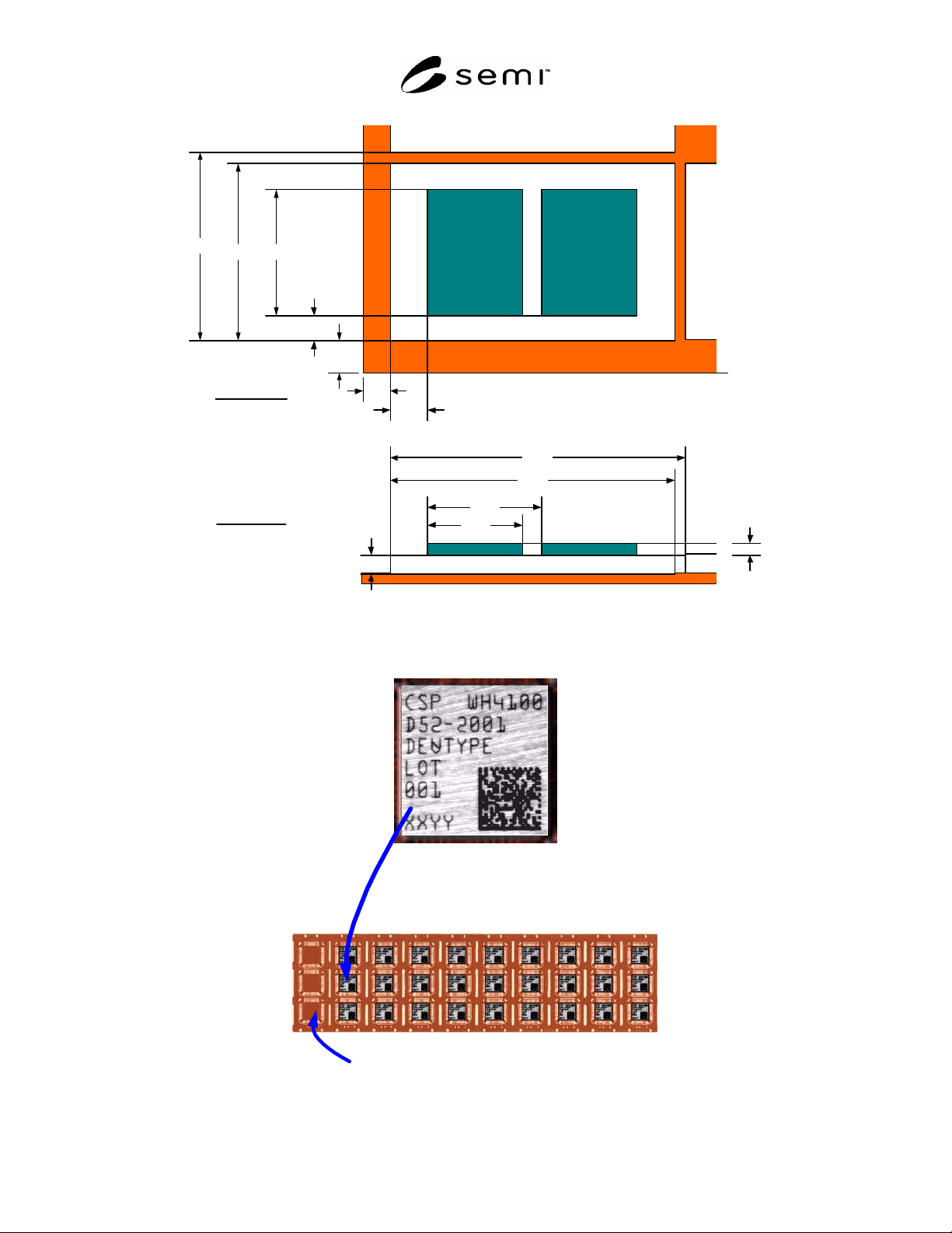
R1-2.2 Figure R1-1 shows a portion of the layout for the strip in the example above. The strip contains “SRAM”
devices with “Flash” devices stacked on top of them.
R1-2.3 Figure R1-2 illustrates one DeviceId element of the map.
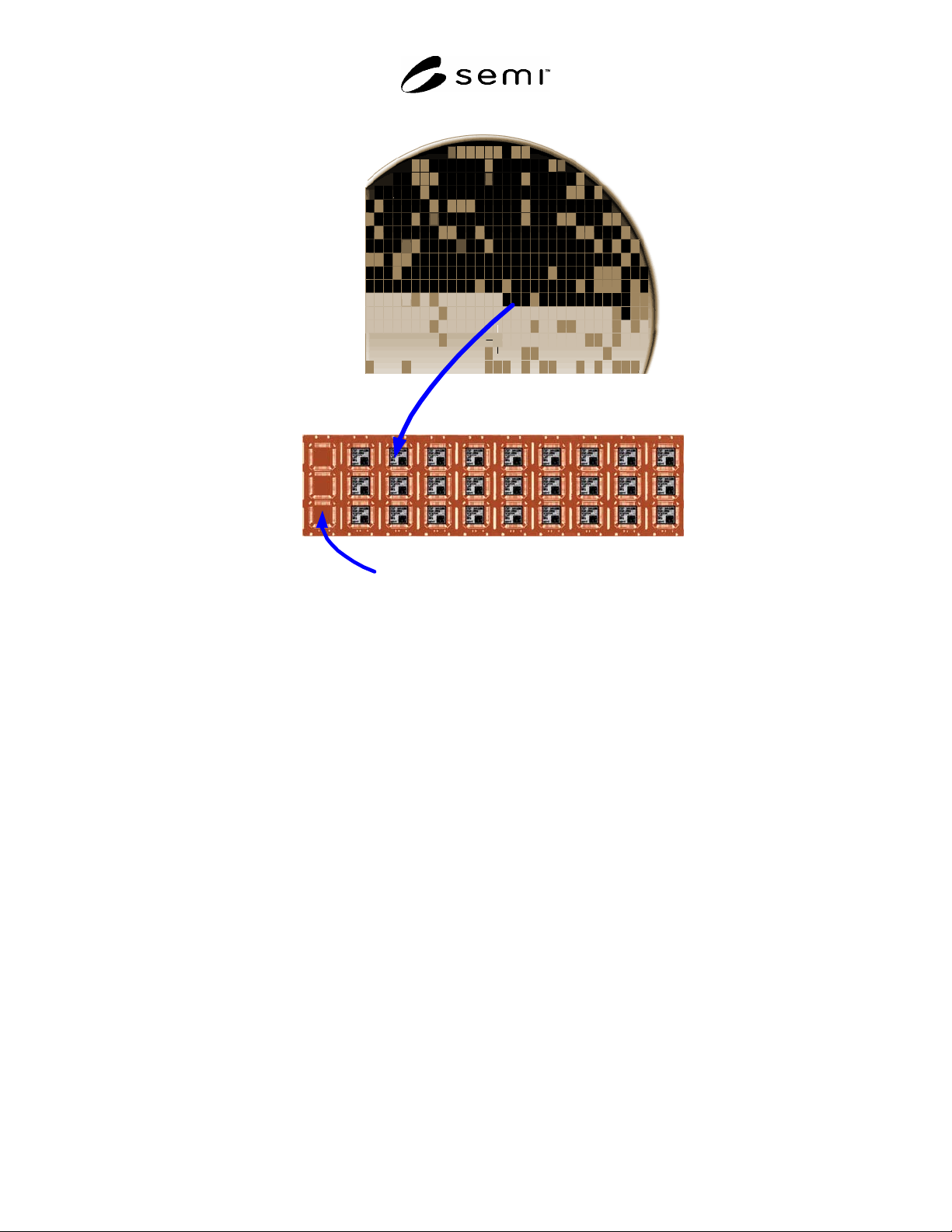
R1-2.4 Figure R1-3 illustrates one Transfer element of the map.
SEMI E142-0705 © SEMI 2005 24
SRAM
FlashFlash
30.00
75.00
78.00
33.00
46.67
49.67
3.00
5.00
SRAM Layout
Dimension (X=32, Y =8)
LowerLef t (X=7.00, Y =8.33)
StepSize (X=78.00, Y=49.67)
Dev iceSize (X=75.00, Y =46.67)
Height = 5.00
ZOrder = 0
25.00
7.00
8.33
Flash Layout
Dimension (X=2, Y =1)
LowerLef t (X=10.00, Y=6.67)
StepSize (X=30.00, Y=0.00)
Dev iceSize (X=25.00, Y =33.0)
Height = 3.00
ZOrder = 1
6.67
10.00
Figure R1-1
Strip Map Example – Layout
Strip
X = 1
Y = 1
OriginLocation (0,0) ="LowerLeftTop"
DeviceId
Figure R1-2
Strip Map Example – DeviceIdMap
SEMI E142-0705 © SEMI 2005 25
Strip
Wafer
OriginLocation(0,0) = "LowerLeftTop"
FX = 20
FY = 12
TX = 2
TY = 3
Figure R1-3
Strip Map Example – TransferMap
NOTICE: SEMI makes no warranties or representations as to the suitability of the standards set forth herein for any
particular application. The determination of the suitability of the standard is solely the responsibility of the user.
Users are cautioned to refer to manufacturer's instructions, product labels, product data sheets, and other relevant
literature, respecting any materials or equipment mentioned herein. These standards are subject to change without
notice.
By publication of this standard, Semiconductor Equipment and Materials International (SEMI) takes no position
respecting the validity of any patent rights or copyrights asserted in connection with any items mentioned in this
standard. Users of this standard are expressly advised that determination of any such patent rights or copyrights, and
the risk of infringement of such rights are entirely their own responsibility.
Copyright by SEMI® (Semiconductor Equipment and Materials
International), 3081 Zanker Road, San Jose, CA 95134. Reproduction of
the contents in whole or in part is forbidden without express written
consent of SEMI.