semi合集-English.pdf - 第4580页
SEMI D33-0703 © SEMI 2003 2 6.2.3 Measuring Equipment 6.2.3.1 Instrume nt for Driving of BLU 6.2.3.1. 1 In this standar d a DC powe r supply is needed and an inverte r for BLU driving of electro -optical test. It is requ…
SEMI D33-0703 © SEMI 2003 1
SEMI D33-0703
MEASURING METHOD OF OPTICAL CHARACTERISTICS FOR
BACKLIGHT UNIT
This method was technically approved by the Global Flat Panel Display Committee and is the direct
responsibility of the Japanese FPD Materials and Components Committee. Current edition approved by the
Japanese Regional Standards Committee on April 28, 2003. Initially available at www.semi.org May 2003;
to be published July 2003.
1 Purpose
1.1 The electro optical characteristics of backlight unit
(BLU) have a great influence on the characteristics of
LCD like uniformity, luminance and chromaticity etc.
There are many measurement methods for BLU of
electro optical characteristics. It is so different that the
measurement method for BLU in each company (e.g.:
the testing position, test condition, equipment concept
etc.). Therefore, this standard will present the general
measurement method.
2 Scope
2.1 This standard is applicable to BLU for Liquid
Crystal Display (LCD) and the measurement includes
only the optical area. The other areas (Electric
characteristics, Reliability, and so forth) are dealt with
by other SEMI standards.
NOTICE: This standard does not purport to address
safety issues, if any, associated with its use. It is the
responsibility of the users of this standard to establish
appropriate safety and health practices and determine
the applicability of regulatory or other limitations prior
to use.
3 Limitations
3.1 This standard does not include the test of each BLU
component such as: light guide panel, optical film, Cold
Cathode Fluorescent Lamp (CCFL), film
characteristics, and etc.
4 Referenced Standards
4.1 Other Standards
Flat Panel Display Measurement Standard, VESA
FPDM 2.0, June 2001.
Commission Internationale de l’Eclairage (CIE),
“Colorimetry of Self-Luminous Displays-A
Bibliography,” CIE Publication No. 87, 1990.
Commission Internationale de l’Eclairage (CIE),
“Colorimetry,” CIE Publication No. 15.2, 1986.
NOTICE: Unless otherwise indicated, all documents
cited shall be the latest published versions.
5 Terminology
None.
6 The Optical Measurement Method
6.1 The test result of BLU can vary because of the
environment and measurement conditions. Therefore,
the measurement environment and conditions need to
be determined.
6.2 Measurement Setup
6.2.1 Environment conditions:
• Temperature: 25 ± 2°C
• Humidity: 65 ± 20% RH
• Illumination of surrounding: dark room below 10
lux
• Air flow: no wind
6.2.2 Measurement Conditions
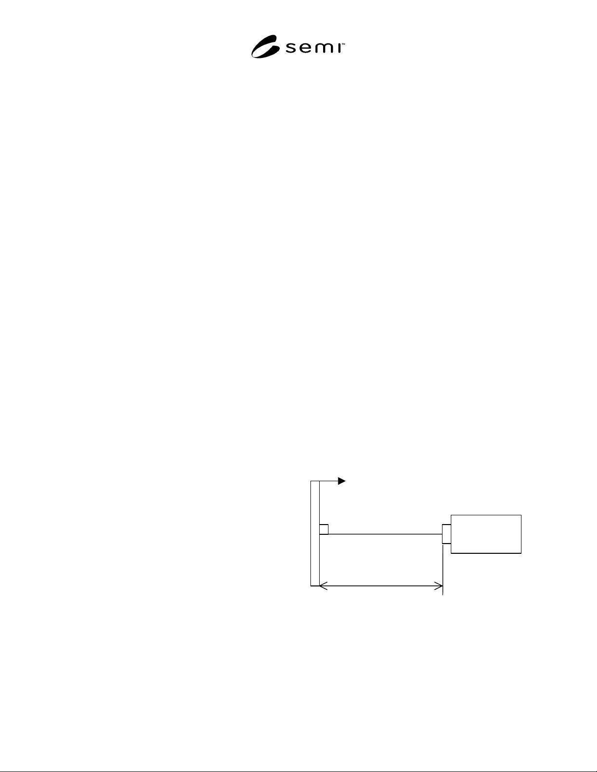
6.2.2.1 The measuring distance is suitable for
500 ± 50 mm at field aperture 1° and the viewing
direction of all tests are 90° ± 1°. This distance is
applied for all measurements in this standard.
90º±1º
500±50mm
Backlight Unit
LMD
Figure 1
The Measuring Configuration for Measuring
Optical Characteristics of BLU
6.2.2.2 Electrical conditions for driving are the typical
lamp current and typical operating frequency. A
nonconductor for jig of BLU is needed and it must be
ground treated to reduce each noise signal.
SEMI D33-0703 © SEMI 2003 2
6.2.3 Measuring Equipment
6.2.3.1 Instrument for Driving of BLU
6.2.3.1.1 In this standard a DC power supply is needed
and an inverter for BLU driving of electro-optical test.
It is required that the DC-power supply has the range of
the output voltage between 0 to 30V and has the range
of the output current between 0 to 8A.
6.2.3.2 Instrument For Optical Measurement
6.2.3.2.1 In this standard, spectroradiometer is needed
for optical test. Spectroradiometer is more adequate
than a filter photometer for BLU color measurement
and it can use filter photometer and spectroradiometer
for luminance measurement.
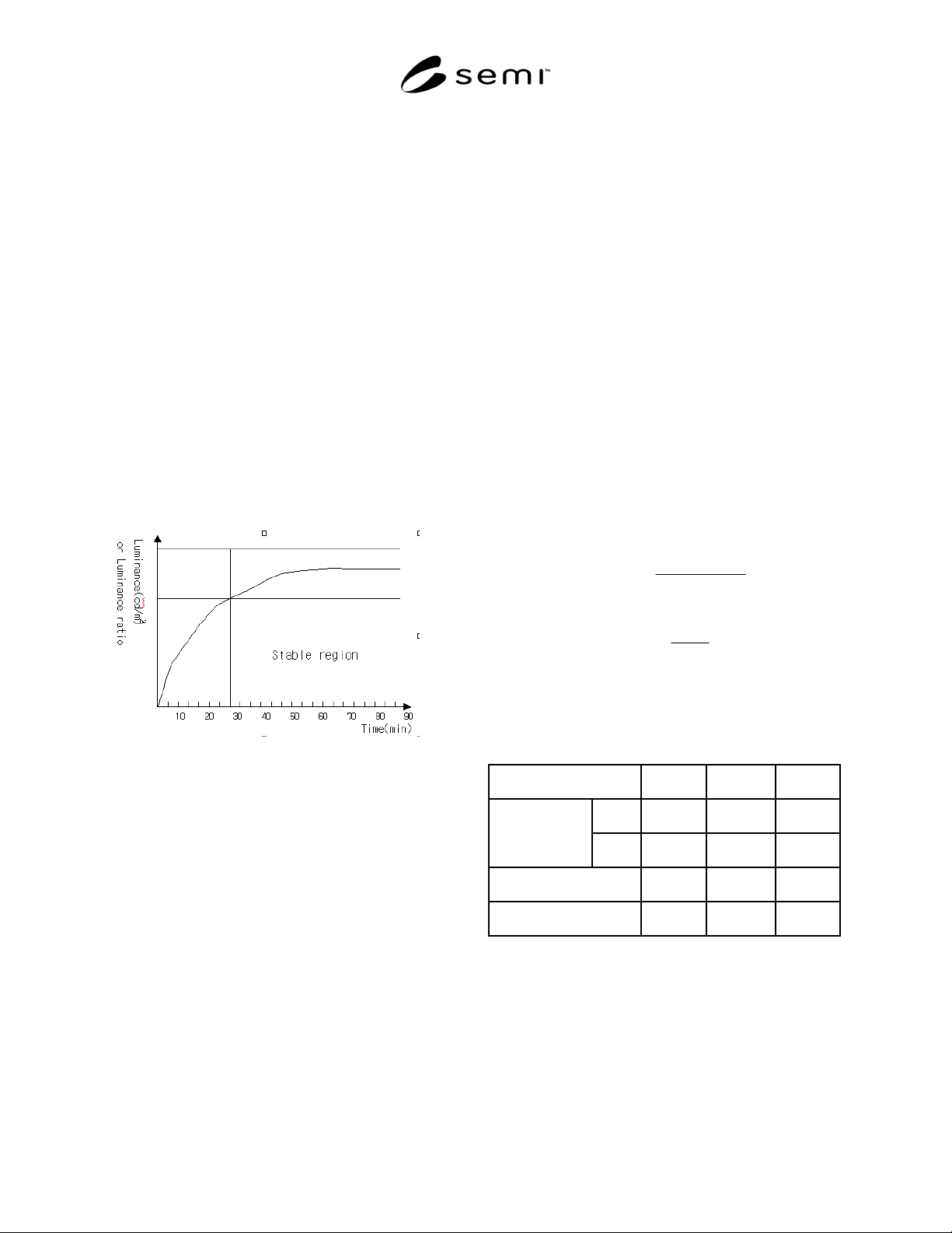
6.2.4 Warm-Up Time
6.2.4.1 Warm-up time is the period from power-on to
saturation of the light intensity. The optical
measurement needs 15 to 30 minutes for a more
accurate measurement in case of luminance and
luminance uniformity.
Figure 2
The Warm-Up Time of BLU
6.2.5 Others
6.2.5.1 It is recommended that the user record the
environment and condition such as: temperature,
humidity, illumination of surrounding, testing distance,
warm-up time, lamp current, etc.
6.3 Measurement Items
6.3.1 The following measurement items are
recommended for BLU, but these items depend on user
requirements if they are specified.
6.3.2 Luminance
6.3.2.1 It is the surface luminance that is detected in all
test areas. Luminance should be expressed in a unit
such as candelas per meter squared [cd/m
2
]. This
luminance is the value measured at one center point or
average value at several testing points. Generally, the
lamp current of BLU should be set to typical lamp
current. If the lamp current value has fluctuation state,
the user should wait by stable state. The measurements
are performed in the dark room under standard
measuring conditions and design viewing direction.
6.3.3 Luminance Uniformity
6.3.3.1 Luminance uniformity is a measure of how well
the luminance remains constant over the surface of the
active area and it is a closely related measurement to
luminance itself. Backlights are particularly liable to
have the non-uniformity characteristics. The measuring
method is similar to the luminance measuring method.
In this measurement, it is important to determine the
testing position. The determination of the testing
position occur some different testing result. In this
standard, we calculate the uniformity with the ratio of
max luminance and min luminance level. The simple
formulas are below. There are two formulas for
uniformity. These formulas explain the non-uniformity
concept, but they very popular with related industry.
Measuring position in luminance uniformity formula:
100)((%)
max
minmax
×
−
=
L
LL
Uniformity
L
L
ratioUniformity
min
max
)( =
NOTE 1: For example, if the maximum luminance is
100 cd/m
2
and the minimum luminance is 80 cd/m
2
the
Uniformity (%) is 20%. And the uniformity (ratio) is 1.25.
Comparison Case A Case B Case C
Max. 200 200 200
Luminance
Min. 140 160 180
Uniformity (%) 30% 20% 10%
Uniformity (ratio) 1.43 1.25 1.11
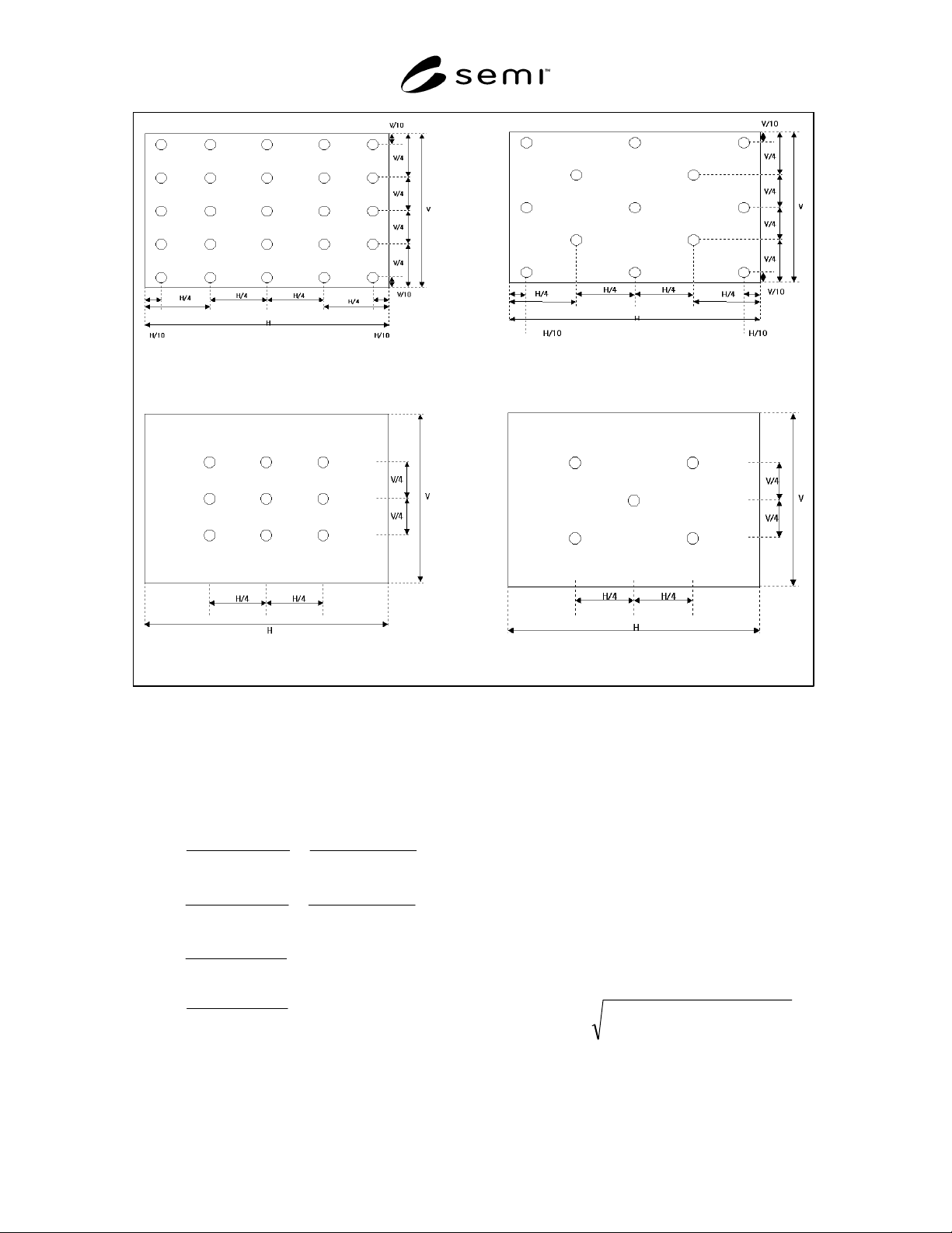
6.3.3.2 For this calculation, there are some positioning
methods and the each user can select the test point
option (the testing number is 5/9/13/25 point).
6.3.3.3 Figures 3a to 3d show each test position and
test number.
SEMI D33-0703 © SEMI 2003 3
Figure 3b
13 measuring points
Figure 3a
25 measuring points
Figure 3c
9 measuring points
Figure 3d
5 measuring points
6.3.4 Color
6.3.4.1 In this standard, color coordinate systems are
the 1931 or 1976 CIE systems. CIE1931 use the ‘x’ and
‘y’ coordination and CIE1976 use u’ and v’
coordination. The relation between CIE1931 to
CIE1976 is below:
36'48'18
'12
36'48'18
'27
3122
9
315
9
'
3122
4
315
4
'
+−
=
+−
=
++−
=
++
=
++−
=
++
=
vu
v
y
vu
u
x
yx
y
ZYX
Y
v
yx
x
ZYX
X
u
6.3.4.2 Generally, because the light source of BLU is a
discontinue wavelength, color should be measured by
spectroradiometer. It is more accurate than filter
colorimeter for color measuring. In this standard, the
measuring distance and viewing direction are the same
with the luminance testing method.
6.3.5 Color Uniformity
6.3.5.1 Color Uniformity is a same meaning with the
Color difference in this standard. It means how the
displays have the consistent chromaticity. In case of the
color uniformity, we use the u’ and v’ coordinates from
CIE1976. The reference point is center position. It is
referenced the ∆u’v’ formula.
The formula is below:
)()(
'
2
'
1
'
2
'
1
''
22
vvuu
vu
−−
+=∆
6.3.5.2 There are some positioning methods for color
uniformity test. It is the same point with luminance