semi合集-English.pdf - 第356页
SEMI E51-0200 © SEMI 1995 , 2000 2 5.1.2 at m — atm o spheric conditions , 1 4.7 psi at sea level 5.1.3 C PVC — chlorin ated polyv i ny l chloride 5.1.4 Cu — copper 5.1.5 EP — electropolished 5.1.6 Galv. — galvanized 5.1…

SEMI E51-0200 © SEMI 1995, 20001
SEMI E51-0200
GUIDE FOR TYPICAL FACILITIES SERVICES AND TERMINATION
MATRIX
This guide was technically approved by the Global Facilities Committee and is the direct responsibility of the
North American Facilities Committee. Current edition approved by the North American Regional Standards
Committee on December 15, 1999. Initially available at www.semi.org January 2000; to be published
February 2000. Originally published in 1995; previously published February 1998.
1 Purpose
1.1 The objectives of this guide are to ensure a timely
and cost-effective tool installation with minimum
impact on the existing customer facilities, systems, and
services, and to insure that the quality of facilities
supplied (e.g., water, gases, chemicals, electricity) is
not compromised once internal to the tool.
1.2 This guide provides the equipment supplier with
an understanding of the facilities available at the point
of connection (POC) at the “typical” customer site. If
these typical facility services are considered by tool
manufacturers during their tool design, additional cost
and lead times associated with customizing each tool
installation can be minimized resulting in reduced costs
to build and install semiconductor equipment.
2 Scope
2.1 This document does not include site-specific
conditions. The Typical Facilities Services and
Termination Matrix Example—United States (see Table
1) identifies utilities, performance, and connections at
typical semiconductor facilities. When site
specifications differ, the user should create a Site-
Specific Facilities Services and Termination Matrix
(see Table 2) that is submitted with the request for a
quote. Each tool should be supplied in a “facility
ready” state. This document represents the range of
conditions in which equipment should be capable of
operating.
2.2 This guide does not purport to address safety
issues, if any, associated with its use. It is the
responsibility of the users of this guide to establish
appropriate safety and health practices and determine
the applicability of regulatory limitations prior to use.
3 Impact
3.1 A reference to this guide and the Typical Facilities
Services and Termination Matrix (see Table 1) or a
completed Site-Specific Facilities Services and
Termination Matrix (see Table 2) should be included
with other applicable tool purchase specifications.
When the supplier receives these documents, a dialogue
can be established to resolve any installation issues
prior to customer purchase or tool installation. Any
additional facility requirements not identified should be
determined when the tool quote is reviewed.
4 Referenced Standards
4.1 SEMI Standards
SEMI E6 — Facilities Interface Specifications
Guideline and Format
SEMI E7 — Specification for Electrical Interfaces for
the U.S. Only
SEMI E30 — Generic Model for Communications and
Control of Manufacturing Equipment (GEM)
SEMI E33 — Specification for Semiconductor
Manufacturing Facility Electromagnetic Compatibility
SEMI E49 — Guide for Standard Performance,
Practices, and Sub-Assembly for High Purity Piping
Systems and Final Assembly for Semiconductor
Manufacturing Equipment
SEMI F47 — Specification for Semiconductor
Processing Equipment Voltage Sag Immunity
4.2 ANSI Standard
1
ANSI B16.5 — Steel Pipe Flanges, Flanged Valves and
Fittings, as it refers to 150 lb. flanges
4.3 IEEE Standards
2
IEEE 1100 — Recommended Practice for Powering
and Grounding Sensitive Electronic Equipment (IEEE
Emerald Book)
4.4 NFPA Document
3
NFPA 70 — National Electrical Code
5 Terminology
5.1 Acronyms and Abbreviations
5.1.1 amb — ambient temperature conditions
1 American National Standards Institute (ANSI), 11 W. 42nd Street,
New York, NY 10036
2 Institute of Electrical and Electronic Engineers (IEEE), 445 Hoes
Lane, P.O. Box 1331, Piscataway, NJ 08855-1331
3 National Fire Protection Association (NFPA), 1 Batterymarch Park,
P.O. Box 9101, Quincy, MA 02269-9101

SEMI E51-0200 © SEMI 1995, 2000 2
5.1.2 atm — atmospheric conditions, 14.7 psi at sea
level
5.1.3 CPVC — chlorinated polyvinyl chloride
5.1.4 Cu — copper
5.1.5 EP — electropolished
5.1.6 Galv. — galvanized
5.1.7 Hg — mercury
5.1.8 kPa — kiloPascals
5.1.9 µ — micron
5.1.10 NFPA — National Fire Protection Association
5.1.11 NPT — National Pipe Thread (U.S. Standard)
5.1.11.1 FNPT — Female National Pipe Thread
5.1.11.2 MNPT — Male National Pipe Thread
5.1.12 NW Flange — ISO NW flange
5.1.13 P. Flange — ANSI B16.5 pipe flange (for the
purpose of this guide)
5.1.14 PFA — Perfluoralkoy, resin
5.1.15 POC — point of connection (POC is the point
where the facility utility connects to the exterior of the
tool.)
5.1.16 POU — point of use
5.1.17 PP — Polypropylene
5.1.18 psia — pounds per square inch, absolute
5.1.19 psig — pounds per square inch, gauge
5.1.20 PVC — Polyvinyl Chloride
5.1.21 PVDF — Polyvinylidene Fluoride
5.1.22 RES. — resistivity
5.1.23 S.M. Flange — sheet metal flange
5.1.24 SS — stainless steel
5.1.25 Stub — pipe or tube stub
6 Typical Facilities Services and Termination
Matrix
6.1 This section of the guide identifies utilities,
performance and connections at typical semiconductor
facilities. This includes a Typical Facilities Services
and Termination Matrix Example—United States (see
Table 1). The guide identifies typical utilities and is not
intended to be limited to the listed utilities. A Site-
Specific Facilities Services and Termination Matrix
(see Table 2) is also provided to document differences
from Table 1 utilities.
6.2 The following is an explanation of the table
headings in the Typical Facilities Services and
Termination Matrix.
6.2.1 Utilities — This is a list of process or process-
related services typically found in semiconductor
facilities. The list is divided into water service, gas
service, drains, bulk chemical distribution, exhaust and
electrical services.
6.2.2 Supply Temperature — Temperature and ranges
are measured in °C (°F). Equipment or tool cooling
systems should be sized to accommodate these ranges.
6.2.3 Supply/Return Pressure — Pressure and ranges
are measured in kPa (psig). Where possible, equipment
should be designed to operate at lower pressure which
reduces energy and safety risks. Regulators should be
specified by the customer and provided with the tool by
the supplier.
6.2.4 Filtration — Filtration provides an indicator of
particle size expectation at POC to the tool. The
fabrication and quality of point of use (POU) filtration
should be specified by the customer and provided with
the tool by the supplier.
6.2.5 Specification — The specification column is a
condensed version of typical customer specifications.
The column should be used by customers to specify
service quality at POC to the tool. Specified quality
should not be compromised or lessened in any way
internally by the supplier’s tool. When the tool
purchase specification is prepared, expanded, and
detailed, quality requirements should be documented.
6.2.6 POC Material — Material that the facility
typically uses for connections to tools. Additional
material quality characteristics should be identified in
the tool purchase specification. Interior piping or
tubing should be specified by the customer and
provided with the tool by the supplier to meet or exceed
the facility POC material quality. (See SEMI E49.)
6.2.7 POC Fitting — Compatible connectors are
critical to ensure that a tool is “facility ready” once it
arrives at a customer site. It is recommended that
equipment be supplied with matching connections as
requested by customer.
6.2.8 Notes — Special conditions or exceptions.
7 General Considerations
7.1 In addition to typical utilities, other facility-related
issues should be addressed prior to tool installation.
7.1.1 Point of Connection Locations — Due to age of
construction or design, all semiconductor facilities are
not the same. To interface with equipment or tool,
three suggested POC locations have been determined.
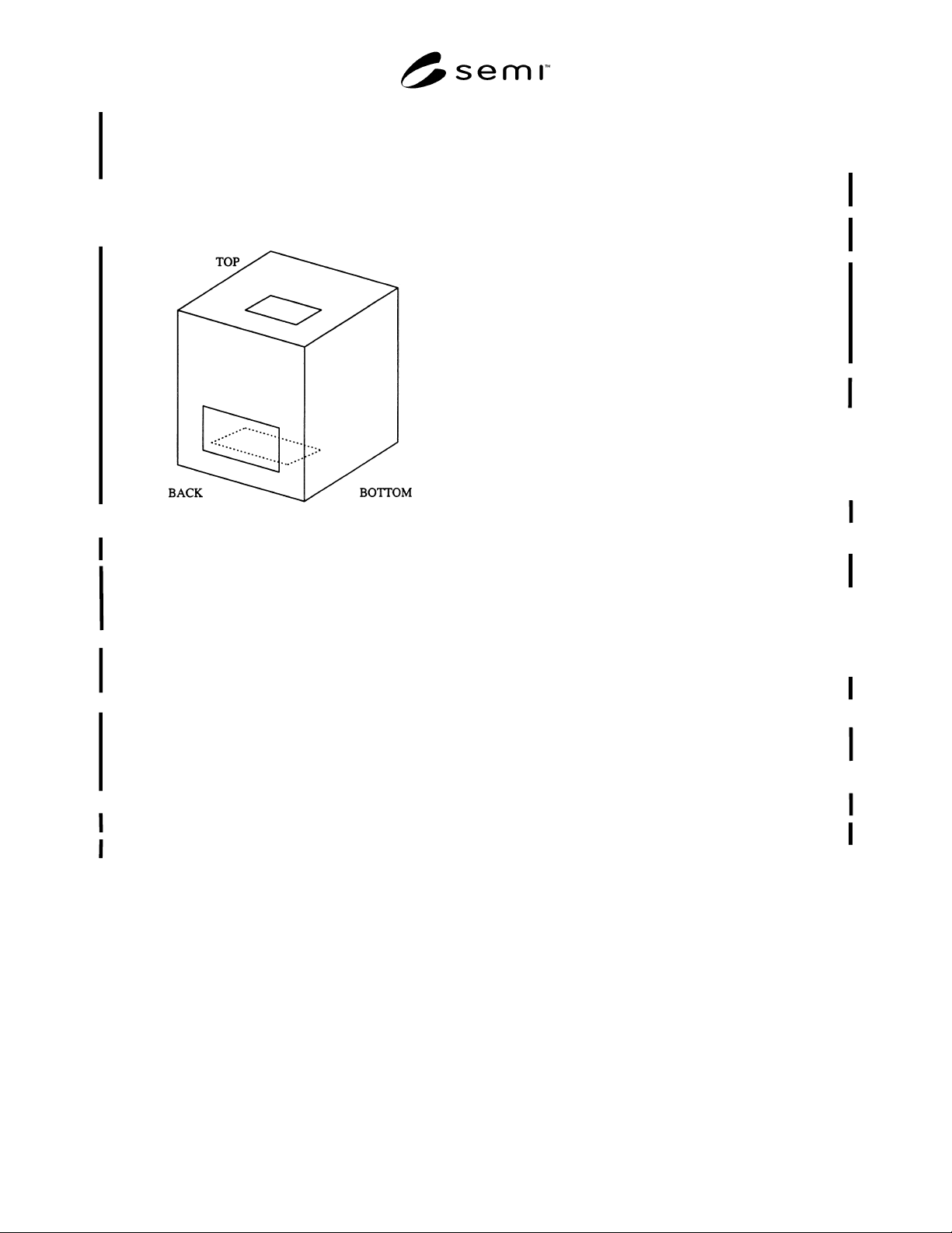
SEMI E51-0200 © SEMI 1995, 20003
(See Figure 1). The POC locations are the top, the
bottom, or the back of the tool. The customer should
identify a POC location in the tool purchase
specification. Suppliers should design tools to allow
for internal routing to all locations, to avoid
customization for every installation.
Figure 1
Three Point of Connection Locations
7.1.2 Seismic — The customer should specify the
applicable earthquake zone for the installation site. The
supplier should provide appropriate seismic restraints
and installation instructions.
7.1.3 Vibration — The customer should specify that
the supplier should provide the vibration sensitivity of
the tool prior to purchase. (See SEMI E6.)
7.1.4 Control and Signal Circuits — The customer
should specify and the supplier should provide control
and signal circuits that when routed external to the tool
are compliant with Article 725, Class 1, Class 2, and
Class 3, Remote Control, Signaling and Power Limited
Control Circuits of the National Electrical Code.
(See NFPA 70.)
Class 1 — No power limitation, 600 volts max.
Class 2 — Derived from listed Class 2 power supply.
Class 3 — Derived from listed Class 3 power supply.
7.1.5 Installation Requirements Provided by Suppliers
— See SEMI E6.
7.1.6 High Purity Distribution Systems Recom-
mendations — See SEMI E49.
7.1.7 POC Labeling — To ensure accurate connection
of facility utilities to each tool POC, the customer
should specify and the supplier should provide labeling
for each POC. Service labeling should match
descriptions listed in the supplier provided installation
documentation. (See SEMI E6.)
7.1.7.1 If required, mechanical POC labels should
include:
• Service purpose,
• Maximum pressure or pressure range, and
• Flow rate (if appropriate).
POC Label Example: Process Purge, Nitrogen, 80 psig
Max.
7.1.7.2 If required, electrical power POC labels should
include:
• Service purpose,
• Voltage & phase, and
• Current (Full load ampere continuous).
POC Label Example: Cryo Pump No. 2, 208 V, 1-
phase, 28.2 FLA
7.1.7.3 If required, control and signaling POC labels
should include:
• Purpose, and
• Class of control (see Section 7.1.4).
POC Label Example: Cryo Pump No. 2 Control, Class
2