semi合集-English.pdf - 第4062页
SEMI F54-1000 © SEMI 2000 7 NOTICE: SEMI makes no warranties or representations as to the suitability of the test method set forth herein for any particular application. T he determination of the suitability of the te st…
SEMI F54-1000 © SEMI 2000 6
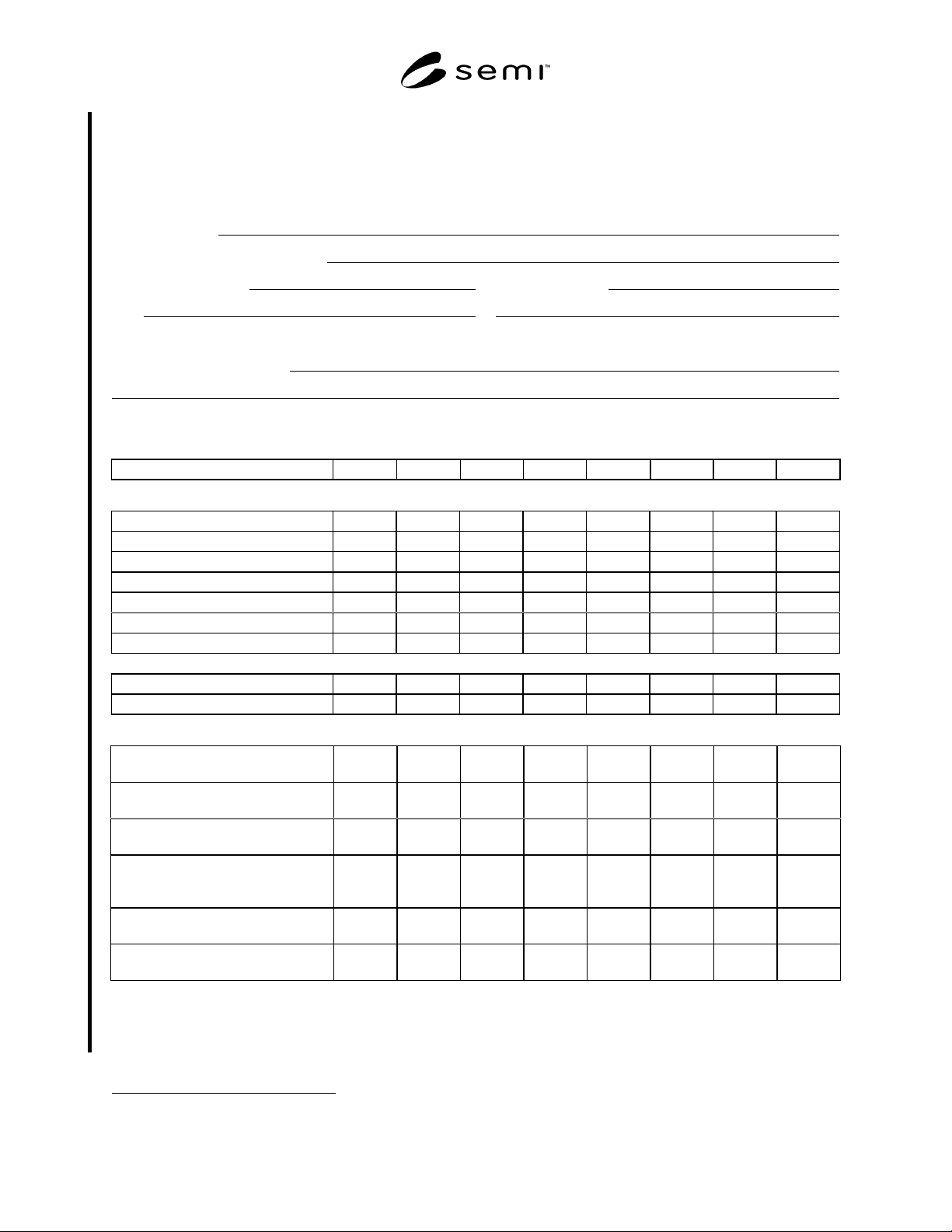
APPENDIX 1
EXAMPLE REPORT FORM
NOTE: The material in this appendix is an official part of SEMI F54 and was approved by full letter ballot procedures on July 13,
2000 by the North American Regional Standards Committee.
A1-1 Test dates:
A1-2 Operator(s) performing test:
A1-3 Serial numbers: Reference instrument
CNC EC
A1-4 Attach flow meter and voltage indicator calibration data as described in Section 11.
A1-5 Data and calculations:
Data Point (Use Additional Sheets as Necessary)
12345678
NaCl Concentration (gm/l)
Flow Rates (cm
3
/s)
EC Aerosol
EC Sheath
EC Excess Air
CNC
Reference Instrument
Make-up Air or
Excess Aerosol Vent
EC Voltage (V)
Particle Size (micrometer)
Measured Particle Concentrations (Particles/cm
3
)
CNC
(1)
(1) Corrected for Transport Loss
(2)*
Reference Instrument
(3)
(3) Corrected for Multiple Charging
(Electrometers Only)
(4)*
(4) Corrected for Transport Loss
(5)*
Counting Efficiency
= (2)/(5)
A1-6 Attach plot of counting efficiency as a function of particle size
A1-7 Lower size sensitivity (micrometer)
∗
___________
∗ Attach calculations.

SEMI F54-1000 © SEMI 20007
NOTICE: SEMI makes no warranties or representations as to the suitability of the test method set forth herein for
any particular application. The determination of the suitability of the test method is solely the responsibility of the
user. Users are cautioned to refer to manufacturer’s instructions, product labels, product data sheets, and other
relevant literature respecting any materials mentioned herein. These test methods are subject to change without
notice.
The user’s attention is called to the possibility that compliance with this test method may require use of copyrighted
material or of an invention covered by patent rights. By publication of this test method, SEMI takes no position
respecting the validity of any patent rights or copyrights asserted in connection with any item mentioned in this test
method. Users of this test method are expressly advised that determination of any such patent rights or copyrights,
and the risk of infringement of such rights, are entirely their own responsibility.
Copyright by SEMI® (Semiconductor Equipment and Materials
International), 3081 Zanker Road, San Jose, CA 95134. Reproduction o
f
the contents in whole or in part is forbidden without express written
consent of SEMI.

SEMI F55-0600 © SEMI 20001
SEMI F55-0600
TEST METHOD FOR DETERMINING THE CORROSION RESISTANCE
OF MASS FLOW CONTROLLERS
This test method was technically approved by the Global Facilities Committee and is the direct responsibility
of the North American Facilities Committee. Current edition approved by the North American Regional
Standards Committee on April 10, 2000. Initially available on www.semi.org May 2000; to be published
June 2000.
1 Purpose
1.1 A mass flow controller (MFC) is often used to
control corrosive gases under unfavorable conditions.
This test method is intended to help differentiate
between MFC designs on the basis of relative resistance
to corrosion-induced failure.
2 Scope
2.1 This test is intended to show the effect of
corrosion caused when a corrosive gas such as HCl is
contaminated by an oxidizer such as atmospheric
moisture. For the purpose of this test HCl is the
preferred test gas, however this test can also be
performed with other gasses. This test method
describes a corrosive gas exposure test for mass flow
controllers. The test is intended to accelerate the
corrosion while simulating conditions that may be
found within process equipment and gas systems in the
semiconductor industry. As the relationship between
corrosion and performance may differ with MFC
design, corrosion is not measured directly. The effects
of corrosion are detected by observing changes in MFC
calibration and other operating parameters.
2.2 This standard does not purport to address safety
issues, if any, associated with its use. It is the
responsibility of the users of this standard to establish
appropriate safety and health practices and determine
the applicability of regulatory limitations prior to use.
3 Limitations
3.1 This test method should not be expected to yield
comparable quantitative results from one test facility to
another.
3.2 Results may be compromised by the methods used
to construct the apparatus.
3.3 This test is designed to be a destructive test. The
MFC tested will be destroyed. This test is intended
only for MFCs manufactured for use in HCl or a similar
highly corrosive gaseous environment. MFCs
manufactured for non-corrosive service may develop
leaks or other catastrophic failures if tested by this
method. For practical reasons in constructing and
operating the test bed, test samples may be limited to
100 sccm N
2
equivalent full scale (FS) flow.
3.4 This method does not measure corrosion directly
by analyzing or inspecting the gas-wetted surfaces
following exposure to a corrosive. No attempt is made
to detect particles in the exit gas stream resulting from
the corrosion process.
4 Referenced Documents
SEMI F1 — Specification for Leak Integrity of High-
Purity Gas Piping Systems and Components
NOTE 1: As listed or revised, all documents cited shall be the
latest publications of adopted standards.
5 Terminology
5.1 Acronyms and Abbreviations
5.1.1 DUT — device under test
5.1.2 FS — full scale
5.1.3 kPa — kiloPascal
5.1.4 MFC — mass flow controller
5.1.5 MFM — mass flow meter
5.1.6 ppbv — parts per billion by volume
5.1.7 ppmv — parts per million by volume
5.1.8 sccm — standard cubic centimeters per minute
using a standard temperature of 0° C and a standard
pressure of 101.32 kPa.
5.2 Definitions
5.2.1 actual flow — for the purpose of this standard,
the output value of the reference flowmeter.
5.2.2 ambient temperature — the temperature of the
medium surrounding the device. Under ordinary
laboratory benchtop conditions, ambient temperature is
the temperature of the room.
5.2.3 indicated flow — the electrical output of the
device under test (DUT).
5.2.4 valve drive — electrical output from the DUT
which is analogous to the level of power supplied to the