semi合集-English.pdf - 第6004页
SEMI P43-0304 © SEMI 2004 13 with approximatel y the same width, such that 1D- linearity does not significantly affect the 2D value. 8.3.1.1 As an example, Figure 19 illustrates how a feature width d eviation co uld affe…
SEMI P43-0304 © SEMI 2004 12
8.2.6.2 1D metrology techniques for measuring OPC
are not
considered within this document’s scope. As a
good reference the reader is referred to for example
Yonekura et al., (Toppan, PMJ2001, SPIE Proceeding
Vol. 4409 p. 204)
NOTE 39: Edge roughness may have an important influence
on the 1D determination of OPC’d features, such that contour
averaging may be necessary to produce a meaningful result.
(a)
(b)
(c)
(d)
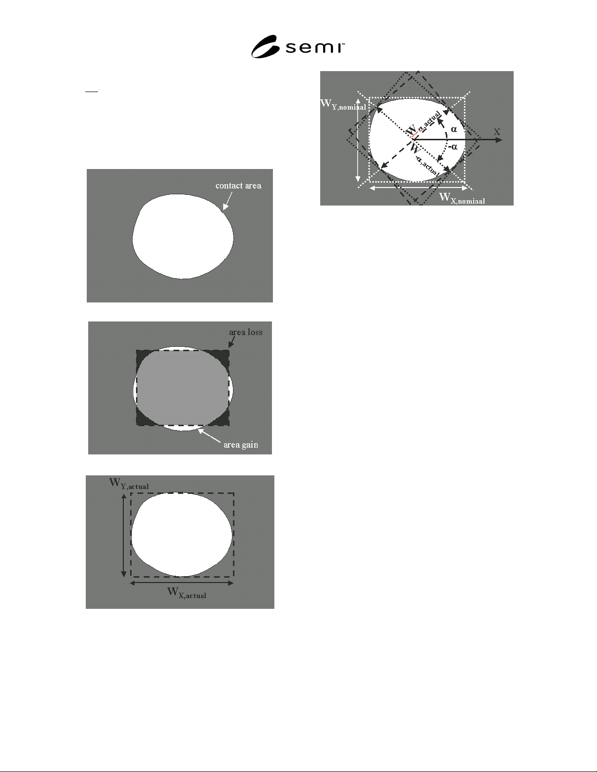
Figure 18
2D Quantification of a contact hole
by contact area,
by area gain and area loss
(dotted line is nominal contact),
by X and Y width (dashed line is smallest rectangle
encompassing the actual contact),
by diagonal width (white dotted lines are the
nominal contact and its diagonals confined by ± α,
where α = arctan(W
Y,nominal
/W
X,nominal
) )
8.2.7 Uniformity of 2D Qualification Parameters
8.2.7.1 In principle all 2D qualification parameters, as
defined above, may vary across the mask. By analogy
to the transition from feature width to feature width
uniformity, any 2D qualification parameter may be
additionally characterized by uniformity. Below, as an
example, corner area difference uniformity is
elaborated.
8.2.7.2 corner area difference uniformity — the spread
of the distribution of the corner area difference of all
mask features selected as described below. To be stated
as mandatory information in addition to that of corner
rounding (Section 8.2.3.1) and also adopting the same
DEFAULTS:
• the criterion used (range, 3-sigma, maximum area
difference, etc.), where sigma stands for standard
deviation.
(Recommendation: before 3-sigma is relevant, the
distribution needs to be “normal” or “near normal”,
and the number of measurements should be > 30.)
• The considered area of interest on the mask.
8.3
Corrected True Values
8.3.1 Some 2D measurements and definitions require
that the mask is on target from a 1D-viewpoint, i.e.,
nominal and actual size coincide for
semi-infinitely
long features present in the region of interest. It is
recommended to limit 2D characterization to features
SEMI P43-0304 © SEMI 2004 13
with approximately the same width, such that 1D-
linearity does not significantly affect the 2D value.
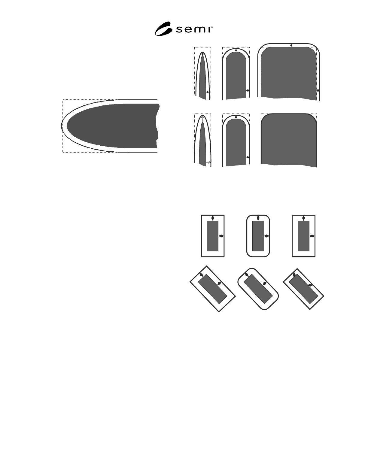
8.3.1.1 As an example, Figure 19 illustrates how a
feature width deviation could affect the line-end.
8.3.1.2 Correction is required for benchmarking
purposes, as described below.
Figure 19
Example where correction of 2D-measurement (here
shown for line-end shortening) for 1D-errors (full
line) provides a different result
8.3.2 2D qualification may be refined by
customer/vendor agreement (or by the user of this
document) by compensating for
• the feature misplacement by alignment (see Section
8.4),
NOTE 40: Pattern alignment is often required and
affects the obtained values. Recommendations on
pattern alignment for 2D qualification will be addressed
in Section 8.4.
• the linewidth deviation (see Figure 20)
b1) by a sizing correction based on the CD mean-
to-target. This correction should be done before
2D-parameter determination,
or
b2) by a sizing correction based on the feature
mean-to-target of the feature considered. This
correction should be done before 2D-parameter
determination, and
• feature linearity errors (feature proximity errors),
using the same sizing corrections as in 8.3.2b, but
based on specific feature width deviation.
8.3.2.1 What was modified and how it was done, is
mandatory information.
NOTE 41: Scaling is not permitted.
NOTE 42: Sizing algorithm to be mentioned: orthogonally,
by circular brush, perpendicularly, etc. (see Figure 21).
DEFAULT is compensation a and b1.
CD
CD
Figure 20
Illustration of correction for 2D features for 1D-
error, according to techniques described under
Section 8.3.2: b1 (upper) and b2 (lower)
Figure 21
Examples of sizing rules for correction:
from left to right: perpendicularly, by circular
brush, orthogonally
8.4 Alignment
8.4.1 Alignment of nominal and actual feature (or
pattern) is only practical when the ROI includes
features where the actual case is a fairly good
approximation to the nominal one.
8.4.2 Alignment can be done by one or more of the
methods shown below. The result obtained by the
different methods may differ. The method is
mandatory information (see Figure 22).
SEMI P43-0304 © SEMI 2004 14
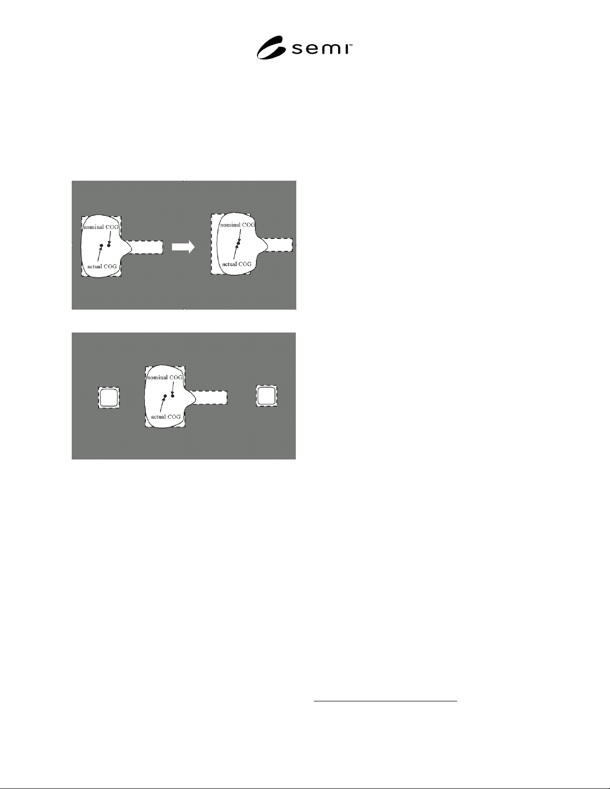
8.4.2.1 In the center-of-gravity (COG) method the
COG of actual and nominal features are superimposed.
8.4.2.2 In the area based method the absolute feature
area deviation between the actual and nominal features
is minimized.
8.4.2.3 In the line-edge based method, alignment is
performed by minimizing the distance between multiple
actual and nominal edges.
(a)
(b)
Figure 22
Alignment of nominal and actual feature
(a) by center of gravity (COG) only, left is the
intended overlay, right is actual overlay from the
COG method, leading to an incorrect result.
(b) by the use of alignment markers.
8.4.3 Alignment is preferably done on dedicated
alignment features (markers), which are symmetric and
not clipped, and their position does not suffer from the
resolution of the imaging process. Crosses are typically
used, as they have X and Y components, which can be
used to correct for rotational error if only one marker
were present.
8.4.4 Additional markers allow for more accurate
rotational compensation and decouple magnification
errors of the feature to be measured from sizing errors.
8.4.5 If no markers are present, one of the methods
above can be attempted on the feature to be measured
or on other features in the ROI, but in such situation
alignment may be less accurate, especially if these
features are clipped (see Figure 22).
8.5
Measured Values
8.5.1 By analogy to Section 7 (1D Mask Qualification
Terminology) a measured qualification parameter can
be defined for every 2D (true) qualification parameter
defined in Section 8.2. In Section 7 this was done
immediately after the definition of the true parameter,
whereas here the measured parameter is treated in a
generic way. Thereby, one 2D qualification parameter
is used for the explanation, i.e., measured corner area
difference and its uniformity, as examples for all other
2D qualification parameters and their uniformity.
NOTE 43: The most critical feature in terms of impact of the
measurement details to the measured values is the size of a
contact near the resolution limit of the metrology tool and of
the mask patterning process.
8.5.2 measured corner area difference — measured
value of corner area difference, stating as mandatory
information, in addition to that of corner rounding
(Section 8.2.3.1):
• calibration method used
4
,
• measurement method used (SEM, optical
reflection, optical transmission, AFM, etc.) and its
resolution limit,
• edge detection algorithm and parameters,
• precision (SEMI P24),
and as optional information :
• measurement tool (vendor, model or any tool
specific options).
8.5.3
measured corner area difference uniformity —
measured value of corner area difference uniformity,
thereby stating as mandatory information in addition to
that of corner area difference uniformity and of
measured corner area difference:
• the number of measurement points used,
and as optional information:
• the spatial distribution of measurement locations,
e.g., by coordinates of measurement locations.
DEFAULT is spread evenly over the measurement
area.
NOTE 44: Edge roughness, either originating from the
process (Note 19 in Section 8.2.2) or from the measurement
technique used, may influence the measurement result. This
is not the case for the two examples treated above, as the
difference parameter filters out the effect of roughness by
4 See reference document in Section 4.2.