semi合集-English.pdf - 第4469页
SEMI D17-0200 © SEMI 1998, 2000 4 symmetric about th e bilateral and facial datum planes, respectively. The top of this volu me is half of z7 above the nominal substrate seating plane and its bottom is z6 above the nomin…
SEMI D17-0200 © SEMI 1998, 20003
float surface are located on the bottom of the cassette
and mate with the two v-rail rollers and one float
surface roller, respectively, mounted on the tool
interface. The facial datum plane v-groove is located
about the facial datum plane through the bottom surface
of the cassette and mates with the facial datum plane
lock pin located on the tool interface shown in Figure 3.
The v-rail roller and the float surface roller are located
by dimensions x15 and x16 relative to the bilateral
datum plane, respectively, shown in Figure 6. The
dimensiona relative to the facial datum plane for the v-
rail rollers are not specified but recommended to be
located furthest from and symmetrical about the facial
datum plane as shown in Figures 3 and 6. The float
surface roller revolute axis must lie on the facial datum
plane.
6.5.2.1 The v-rail and float surface rollers are defined
in Figure 7 and Table 4. Each roller is radially
symmetric about the revolute axis. The rollers are
circumferentially radiused of dimension r8. The
diameter of the rollers is not specified, but the
tangential surface created by dimension r8 must lie on
the horizontal datum plane. The facial datum plane lock
pin radius is equal to r8 and must be positioned into the
facial datum plane v-groove to fully constrain the
cassette to the facial datum plane. The facial datum
plane lock pin is translated out of the facial datum plane
v-groove to allow the cassette to be rolled in and out of
the tool interface. Although only three rollers are
specified, it is recommended to increase the total
number of rollers so that the cassette is fully supported
while being loaded and unloaded to the tool interface.
All rollers, except for the v-rail and float roller, must be
positioned so that the tangent of the r8 dimension lies
below the horizontal datum plane.
6.5.2.2 The three features on the botto m of the cassette
that mate with the rollers and lock pin must provide a
lead-in capability that corrects a cassette misalignment
of up to 10 mm (0.4 in.) in any horizontal direction,
although 15 mm (0.6 in.) is recommended. The v-rail
and facial datum plane v-groove are not specified but
recommended to be inverted v-shaped grooves. The v-
rail is recommended to extend the full length of the
cassette from the cassette front to the cassette rear. The
float surface is not specified but recommended to be a
flat surface extending the full length of the cassette
from the cassette front to the cassette rear. The
exclusion zones for these features are shown in Figures
3 and 6 and specified by dimensions x15 and x16
through x22.
6.5.3 Cassette Physical Alignment Interface Type C —
To be developed.
6.6 Conveyor Rails — If the cassette is to be
transported on roller conveyors, each conveyor rail
should extend the maximum distance from front to
back. The exclusion zones for conveyor rails are shown
in Figures 3 and 6 and specified by dimensions x13 and
x22 and extend to the outer boundary of the cassette.
6.7 Conveying Surface — If the cassette is to be
transported on roller conveyors that support the entire
bottom of the cassette, the bottom surface excluding the
v-rail, v-groove, and float roller zones is to be used.
The location of this surface with respect to the
horizontal datum plane is specified by dimension z3.
6.8 Substrate Orientation — The s ubstrates must be
horizontal when the carrier is placed on the coupling.
6.9 Cassette Sides and Rear — Fig ure 2 shows a top
view of the boundaries of the cassette side domains
(which contain the parts of the cassette higher than z4
above the horizontal datum plane and lower than z9
above the top substrate). Table 1 defines the dimensions
shown in this and following figures.
6.10 Cassette Top — The boundaries of the cassette
top domain contain any part of the cassette hither than
z9 above the top substrate.
6.11 Cassette Bottom — Figure 3 shows a bottom
view of the boundaries of the cassette bottom domain
(which contains any part of the cassette lower than z4
above the horizontal datum plane). When the cassette is
fully down, the cassette placement sensing pads must
be z2 above the horizontal datum plane.
6.12 Vertical Dimensions
6.12.1 Figure 4 shows the vertical dimensions of the
left half of the cassette as viewed from the rear. Note
that z5 (the height of the bottom nominal substrate
seating plane above the horizontal datum plane) and z8
(the distance between adjacent nominal substrate
seating planes) are given as reference dimensions with
no tolerance. This means that the sum of actual height
variations in the cassette from the horizontal datum
plane to the mizo tooth or slot holding each substrate
must be contained within the tolerance of z6 with no
further stack-up at each higher substrate.
6.12.2 The open space for the substrate extraction
volume is indicated by dimensions x6 and y7 and is
symmetric about the bilateral and facial datum planes,
respectively. The top of the extraction volume is z7
above the nominal substrate seating plane and its
bottom is half of the minimum z7 dimension above the
nominal substrate seating plane. The cassette must give
extra horizontal clearance once the substrate is picked
up from wherever it ends up (within the bounds of the
substrate pick-up volume) after transport in the cassette.
6.12.3 The open space for the substrate set-down
volume is indicated by dimensions x5 and y6 and is
SEMI D17-0200 © SEMI 1998, 2000 4
symmetric about the bilateral and facial datum planes,
respectively. The top of this volume is half of z7 above
the nominal substrate seating plane and its bottom is z6
above the nominal substrate seating plane. The
substrate should be placed within the bounds of the
substrate set-down volume to avoid touching the edge
of the substrate to the side of the cassette.
6.12.4 The substrate pickup zone is defined by an area
indicated by dimensions x5 and y5 and is symmetric
about the bilateral and facial datum planes,
respectively. Its top and bottom are the upper and lower
tolerance of z6 around the nominal substrate seating
plane. If a substrate is placed in the substrate set-down
volume and is then pushed to the rear of the cassette,
then the entire bottom of the substrate must be
contained in the substrate pick-up zone.
6.13 Particle Generation — The cassette will not add
more than 0.05 particles/cm
2
of a size ≥ 0.5 µm (PSL
equivalent) per substrate pass per shipping cycle. The
shipping cycle is to be defined by the customer.
6.14 Inner and Outer Radii — All concave features
may have as much as a 1 mm (0.04 in.) radius to allow
for cleaning and to prevent contaminant build-up. All
required convex features (such as the robotic handling
flanges and the corners of the cassette top and bottom
domains) must also have a minimum radius of 1 mm
(0.04 in.) to prevent large stress contacts of the cassette
that might cause wear and particles.
6.15 Dimensional Tolerances — Width (W), Length
(L), and Height (H): ± 5 mm
6.16 Special Design Features
6.16.1 Compatible with automated cl eaning tools.
6.16.2 External features that are comp atible with
material handling systems such as, but not limited to,
Guided Vehicles, Stocker, and Conveyors.
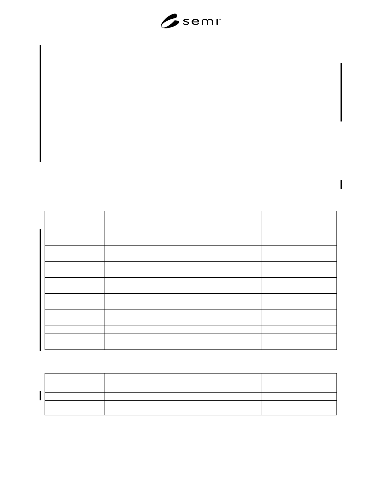
Table 1 Cassette Registration Type A Coupling Pin Dimensions
Symbol
Used
Shown In Dimensions Description Algebraic Relation or Value
d1 Figure 5 diameter of pin centered on the center axis line = 12 ± 0.05 mm
(0.4724 ± 0.002 in.)
r2 Figure 5 radial distance from the center axis line to the origin of shoulder
radius r5
= 6 mm
(0.2362 in.)
r3 Figure 5 radial distance from the intersection of the center axis line and z13 to
the top of the pin
= 15 ± 0.05 mm
(0.5906 ± 0.002 in.)
r4 Figure 5 blend radius for the intersection of r3 and r5 = 2 ± 0.1 mm
(0.0787 ± 0.004 in.)
r5 Figure 5 radial distance from the intersection of the horizontal datum plane
and r2 to the far shoulder of the pin
= 15 ± 0.05 mm
(0.5906 ± 0.002 in.)
r6 Figure 5 blend radius for the intersection of r5 and d1 = 2 ± 0.1 mm
(0.0787 ± 0.004 in.)
r7 Figure 5 roughness (R
a
) as defined in ISO 4287
0.30 µm (12 µin.) max.
z13 Figure 5 vertical distance from the horizontal datum plane to the origin of top
radius r3
= 2 ± 0 mm
(0.08 in.)
Table 2 Cassette Registration Type B Roller Pin Dimensions
Symbol
Used
Shown In Dimensions Description Algebraic Relation or Value
r8 Figure 7 radius about roller circumference revolved about the revolute axis = 4.8 ± 0.12 mm
r9 Figure 7 radius of roller measured from the tangential surface created by r8 to
the revolute axis
≥ 20 ± 0.12 mm
SEMI D17-0200 © SEMI 1998, 20005
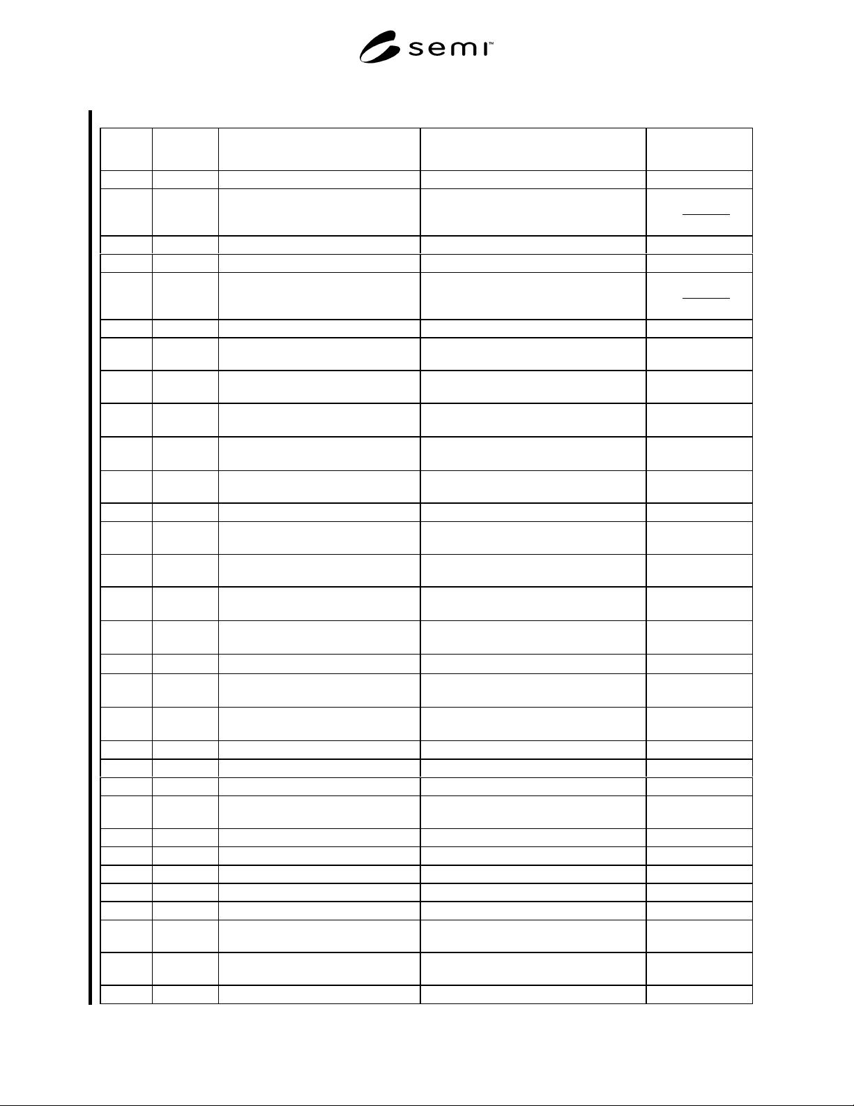
Table 3 Cassette Side Domains
Symbol
Used
Shown In Datum Measured From Boundary or Feature Measured To Algebraic
Relation or Value
r1 Figure 3 center of coupling exclusion zone outside edge of coupling exclusion zone < 15 mm
x1 Figure 2 bilateral datum plane encroachment of cassette side domains
on substrate extraction volume
2
57.0*W
≥
x2 Figure 2 bilateral datum plane outside edge of cassette side domains ≤ W + 37
x3 Figure 2 bilateral datum plane inside edge of rear cassette domains ≥ x1 – 40
x4 Figure 2 bilateral datum plane outside edge of rear cassette domains
2
57.0*W
≥
x5 Figure 2 nominal substrate center line outside edge of substrate pick-up zone ≥ W + 2
x6 Figures 2
and 4
nominal substrate center line encroachment of cassette side domains
on substrate extraction volume
≥ x5
x7 Figure 2 nominal substrate center line outside edge of cassette top and bottom
domain
≤ W + 37
x8 Figure 3 bilateral datum plane inside edge of cassette sensing pad areas
= W * 0.71 ±
5.0 mm
x9 Figure 3 bilateral datum plane outside edge of cassette sensing pad
areas
= W * 0.78 ±
5.0 mm
x10 Figure 4 bilateral datum plane encroachment of cassette top domain on
robotic handling flange space
≤ W * 1.02
x11 Figure 4 bilateral datum plane far side of robotic handling flanges ≤ W * 1.05
x12 Figure 3 bilateral datum plane inside edge of conveyor rail exclusion
zones
≥ W * 0.752
x13 Figure 3 bilateral datum plane outside edge of conveyor rail exclusion
zones
≤ W * 0.877
x14 Figure 3 bilateral datum plane center of coupling exclusion zones
= W * 0.9455 ±
0.1 mm
x15 Figures 3
and 6
bilateral datum plane centerline of v-rail roller
= W * 0.815 ±
0.2 mm
x16 Figure 6 bilateral datum plane centerline of float roller
= x19 ± 2.0 mm
x17 Figure 3 bilateral datum plane inside edge of facial datum plane v-
groove
= W * 0.0245 ±
0.2 mm
x18 Figure 3 bilateral datum plane outside edge of facial datum plane v-
groove
= W * 0.020 ±
0.2 mm
x19 Figure 6 bilateral datum plane left edge of v-groove exclusion zone ≥ W * 0.069
x20 Figure 6 bilateral datum plane right edge of v-groove exclusion zone ≥ W * 0.109
x21 Figure 6 bilateral datum plane inside edge of float roller exclusion zone ≤ W * 0.742
x22 Figure 6 bilateral datum plane outside edge of float roller exclusion
zone
≥ W * 0.884
y1 Figure 2 facial datum plane encroachment of cassette side domain ≥ L * 0.031
y2 Figure 2 facial datum plane encroachment of cassette side domain ≤ L * 0.454
y3 Figure 2 facial datum plane encroachment of cassette side domain ≥ L * 0.515
y4 Figure 2 facial datum plane encroachment of cassette side domain ≤ L * 0.938
y5 Figure 2 facial datum plane outside edge of substrate pick-up volume ≤ L + 1
y6 Figure 2 facial datum plane encroachment of cassette side domains
on substrate set-down volume
≥ L + 1
y7 Figure 2 facial datum plane encroachment of cassette side domains
on substrate extraction volume
≥ L + 3
y8 Figure 2 facial datum plane boundary of rear cassette domain ≤ L * 1.12