semi合集-English.pdf - 第4441页
SEMI D10-95 © SEMI 1995, 2003 1 SEMI D10-95 (Reapproved 0703) TEST METHOD FOR CHEMICAL DURABILITY OF FLAT PANEL DISPLAY GLASS SUBSTRATES This test method was technic ally reapproved b y the Global Flat Panel Display Comm…
SEMI D9-0303 © SEMI 1994, 2003 4
4.8.4 Poisson’s ratio the ratio between Young’s
modulus and shear modulus.
4.8.5 Vickers hardness — a type of pressure test. A
diamond pyramid indentator with a face angle of 136°
is pressed into the glass surface to find the degree of
hardness by measuring trace indentation on the overall
squareness.
4.9 Electrical Properties
4.9.1 dielectric constant the proportionate dielectric
constant which is the ratio between a vacuum dielectric
constant and the material dielectric constant.
4.9.2 dielectric loss — the phenomenon, or volume, of
(electricity) loss through heat when a dielectric is
introduced to an alternating current.
4.9.3 resistivity — the reciprocal of electric
conductivity.
4.10 pattern surface — the main area where device
patterns can be formed, determined by the orientation
corner, etc.
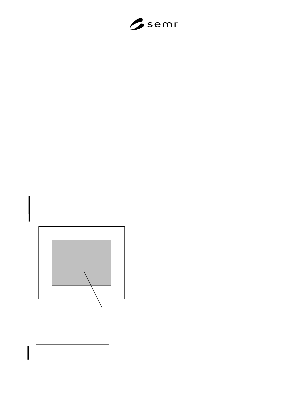
4.11 quality area — the center area to the substrate
where specified substrate quality criteria (primarily
internal defects, surface contamination, surface defects,
waviness, and surface roughness) are applicable.
5 Referenced Documents
SEAJ(Semiconductor Equipment Association of Japan)
Liquid Crystal Display Manufacturing Equipment
Dictionary
2
quality area
Figure 4
Quality Area
2 Semiconductor Equipment Association of Japan, 7-10 Shinjuku 1-
chome, Shinjuku-ku, Tokyo, 160-0022 Japan. Tel:+81-3-3353-7589,
fax:+81-3-3353-7970, http://www.seaj.or.jp
NOTICE: SEMI makes no warranties or
representations as to the suitability of the standards set
forth herein for any particular application. The
determination of the suitability of the standard is solely
the responsibility of the user. Users are cautioned to
refer to manufacturer’s instructions, product labels,
product data sheets, and other relevant literature
respecting any materials mentioned herein. These
standards are subject to change without notice.
The user’s attention is called to the possibility that
compliance with this standard may require use of
copyrighted material or of an invention covered by
patent rights. By publication of this standard, SEMI
takes no position respecting the validity of any patent
rights or copyrights asserted in connection with any
item mentioned in this standard. Users of this standard
are expressly advised that determination of any such
patent rights or copyrights, and the risk of infringement
of such rights, are entirely their own responsibility.
Copyright by SEMI® (Semiconductor Equipment and Materials
International), 3081 Zanker Road, San Jose, CA 95134. Reproduction o
f
the contents in whole or in part is forbidden without express written
consent of SEMI.

SEMI D10-95 © SEMI 1995, 2003 1
SEMI D10-95 (Reapproved 0703)
TEST METHOD FOR CHEMICAL DURABILITY OF FLAT PANEL
DISPLAY GLASS SUBSTRATES
This test method was technically reapproved by the Global Flat Panel Display Committee and is the direct
responsibility of the Japanese FPD Materials and Components Committee. Current edition approved by the
Japanese Regional Standards Committee on April 28, 2003. Initially available at www.semi.org June 2003;
to be published July 2003. Originally published in 1995.
1 Purpose
1.1 This test procedure evaluates quantitatively the
durability of flat panel display (FPD) glass substrates
using reagents employed in FPD production processes.
2 Scope
2.1 This standard may be used by vendors and/or
buyers of glass substrates for FPD.
2.2 This standard defines three methods for testing
chemical durability of various flat panel display
substrates: (Method A) Weight Loss, (Method B) Step
Measurement Using Profilometry, and (Method C)
Surface Haze. Each method provides a measure of the
amount of material that is removed from a substrate
during a controlled chemical reaction sequence. This
sequence is nominally identical for each method.
NOTICE: This standard does not purport to address
safety issues, if any, associated with its use. It is the
responsibility of the users of this standard to establish
appropriate safety and health practices and determine
the applicability of regulatory or other limitations prior
to use.
3 Limitations
3.1 These tests are not applicable to calculating
variations in chemical durability in local areas within a
substrate.
3.2 The calculations assume that all edges are
nominally straight. They do not include adjustments for
corner cuts.
3.3 The chemicals used in these practices are
potentially harmful and should be handled in a fume
hood with the utmost care at all times. Warning -
Hydro- fluoric acid solutions are particularly hazardous.
Precaution: They should not be used by anyone who is
not familiar with the specific preventive measures and
first aid treatments given in the appropriate Material
Safety Data Sheet.
4 Referenced Standards
4.1 SEMI Standard
SEMI D5 — Standard Size for Flat Panel Display
Substrates
4.2 ASTM Document
1
C729 — Test Method for Density of Glass by Sink
Float Comparator
4.3 ISO Document
2
ISO 3274 — Instruments for the Measurement of
Surface Roughness by the Profile Method Contact
(Stylus) Instruments of Consecutive Profile
Transformation Contact Profile Meters, System M
4.4 JIS Documents
3
JIS B0651 — Instruments for the Measurement of
Surface Roughness by the Stylus Method
JIS B7507 — Vernier, Dial, and Digital Callipers
JIS B7601 — Trip Balances
JIS K7105 — Testing Methods for Optical Properties of
Plastics
NOTICE: Unless otherwise indicated, all documents
cited shall be the latest published versions.
5 Terminology
5.1 Definitions
5.1.1 haze — a method to measure the degree of haze
created on the FPD glass substrate surface by a
chemical etch sequence.
1 American Society for Testing and Materials, 100 Barr Harbor
Drive, West Conshohocken, Pennsylvania 19428-2959, USA.
Telephone: 610.832.9585, Fax: 610.832.9555, Website:
www.astm.org
2 International Organization for Standardization, ISO Central
Secretariat, 1, rue de Varembé, Case postale 56, CH-1211 Geneva 20,
Switzerland. Telephone: 41.22.749.01.11; Fax: 41.22.733.34.30,
Website: www.iso.ch
3 Japanese Industrial Standards, Available through the Japanese
Standards Association, 1-24, Akasaka 4-Chome, Minato-ku, Tokyo
107-8440, Japan. Telephone: 81.3.3583.8005; Fax: 81.3.3586.2014,
Website: www.jsa.or.jp

SEMI D10-95 © SEMI 1995, 2003 2
5.1.2 step measurement using profilometry — a
method to measure depths of etching by comparing the
differences in heights between etched and non-etched
parts of a specimen measured by profilometry or an
equivalent method.
5.1.3 weight loss method — a method to calculate
depths of etching by comparing differences in specimen
weights before and after the etch sequence.
6 Apparatus
6.1 For all chemical reactions, the following apparatus
shall be used.
6.1.1 Reaction Vessel
6.1.1.1 Material — Teflon or other suitably etch-
resistant material.
6.1.1.2 Shape and Capacity — Cylindrical wide-
mouthed sealable vessel, suitable for the size and
quantity of samples to be tested.
6.1.2 Thermostatically Controlled Shaker Bath or
Equipment
6.1.2.1 Shaking Stroke — 10 to 60 mm.
6.1.2.2 Shaking Frequency — 30–90/min., controllable
to ± 10/min.
6.1.2.3 Operating Temperature Range — 20 to 150° C,
controllable to ± 1° C.
6.1.3 Oven — Controllable to ± 10° over an operating
range of 50 to 200° C.
6.1.4 Desiccator — Room temperature, with sufficient
capacity and size for all samples to be tested.
6.1.5 Caliper — Per JIS B7507, or equivalent.
6.2 For the measurements, one of the following shall
be used.
6.2.1 Method A — Balance per JIS B7601, or
equivalent.
6.2.2 Method B — Profilometer per ISO 3274, JIS
B0651, or equivalent.
6.2.3 Method C — Haze measurement equipment with
integrating sphere per JIS K7105, or equivalent.
NOTE 1: It is ideal to use haze measurement equipment
which automatically measures total transmittance, diffuse
transmittance, and haze values.
7 Reagents and Materials
7.1 No specific requirement is defined for the reagents
and materials. As long as the test conditions are
reported with the result, any combination of chemical
reagents with any concentration can be used for the test.
The test conditions should reflect actual process
conditions which are specific for the Flat Panel Display
manufacturers. Some reagents suggested for the test are
provided in Related Information 1 as a reference.
7.2 This standard may involve hazardous materials,
operations, and equipment. This standard does not
purport to address all of the safety problems associated
with its use. It is the responsibility of the user of this
standard to establish appropriate safety and health
practices and determine the applicability of regulatory
limitations prior to use.
8 Sample Preparation
8.1 Prepare at least a specimen from a lot of the
substrates to be tested. The specimen is a rectangular
plate about 25 × 50 mm edge length for Methods A and
B, or 40 × 40 mm edge length for Method C.
8.1.1 If they are not already chamfered, specimen
edges and corners should be chamfered slightly to
remove chips and prevent cracking. If repeated tests are
expected, prepare an appropriate quantity of test
specimens.
8.2 Measure edge lengths of the test specimens, and
calculate total surface area, A:
A
=
(
L
×
W
×
2
)
+
{ (
L
+
W
)
×
T
×
2
)}
(
1
)
where
L
=
one edge length of test specimen in cm,
W
=
adjacent edge length of test specimen in cm,
T
=
thickness of test specimen in cm, and
A
=
total surface area of test specimen in cm
2
.
8.3 Clean all test specimens by a method appropriate
for the history of the material. The cleaning method
should not cause any corrosion. Clean the specimens by
an appropriate neutral or alkali detergent for
approximately 10 minutes using an ultrasonic bath.
8.3.1 Rinse them continuously in a stream of deionized
water, having a conductivity of less than 1 µ S/cm, for 1
minute using the ultrasonic bath. Finally, dry them.
8.4 Place all specimens on a clean heat resistant sample
holder. Dry the specimens at 140 ± 10° C for 30
minutes.
8.5 Place all specimens in a desiccator containing silica
gel or calcium sulfate and cool them, for a minimum of
1 hour, to room temperature.
8.6 If Method A will be used, weigh the test specimen
to 0.1 mg or 0.01 mg as required using the balance.
8.7 If Method B will be used, coat about a half portion
of each test specimen by an appropriate coating