semi合集-English.pdf - 第6264页
SEMI G51-90 © SEMI 1990 6 Detail A Corner Relief Hole (Optiona l) Table 2 Leadfr ame Standard Dimension s LEADS PKG. BODY a b c d 44 10 × 10 4.200 3.800 1.170 1 .170 52 10 × 10 4.200 3.800 1.170 1 .170 52 14 × 14 3.735 3…
SEMI G51-90 © SEMI 19905
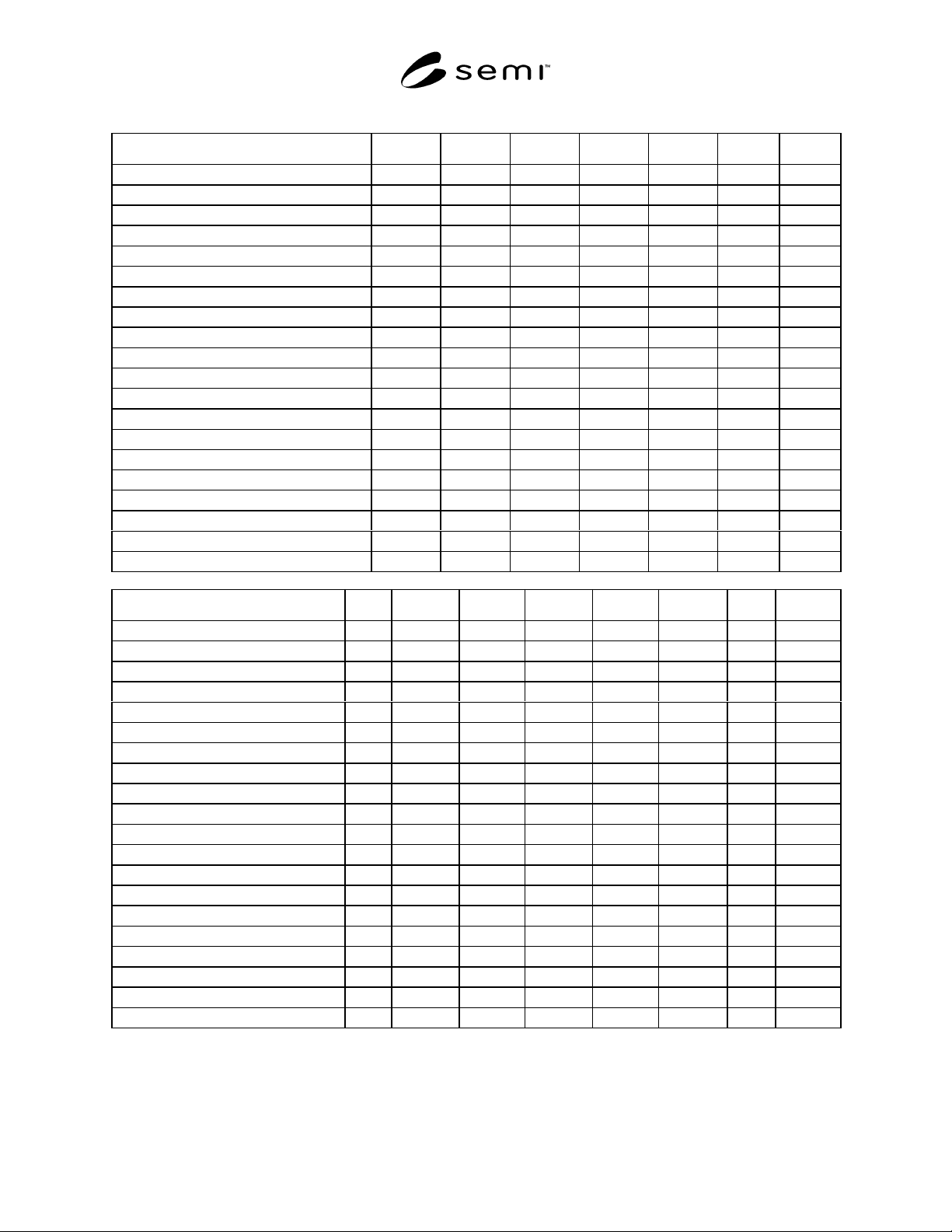
Table 1 Leadframe Standard Dimensions
LEAD COUNT 44525264806480
PACKAGE SHAPE SQUARE SQUARE SQUARE SQUARE SQUARE RECT RECT.
NOMINAL PACKAGE WIDTH (mm) 10.0 10.0 14.0 14.0 14.0 14.0 14.0
NOMINAL PACKAGE LENGTH (mm) 10.0 10.0 14.0 14.0 14.0 20.0 20.0
STRIP LENGTH (mm) 171.2 171.2 158.52 158.52 158.52 158.52 158.5
NO. OF UNITS PER STRIP 8866666
TOOLING DIM A (mm) 7.5 7.5 9.45 9.45 9.45 9.45 9.45
(PROGRESS) C (mm) 21.4 21.4 26.42 26.42 26.42 26.42 26.42
F (mm) 1.5 1.5 1.7 1.7 1.7 1.7 1.7
G (mm) 23.2 23.2 26.0 26.0 26.0 33.1 33.1
(STRIP WIDTH) H (mm) 24.7 24.7 27.7 27.7 27.7 34.8 34.8
I (mm) 20.0 20.0 22.82 22.82 22.82 28.8 28.8
J (mm) 20.0 20.0 22.82 22.82 22.82 22.82 22.82
K (mm) 5.18 5.18 7.18 7.18 7.18 7.18 7.18
L (mm) 5.18 5.18 7.18 7.18 7.18 10.18 10.18
DAMBAR WIDTH (mm) 0.4 0.4 0.4 0.4 0.4 0.4 0.4
EXP. SLOT WIDTH (mm)
1) BETWEEN FRAMES 1)0.3 1)0.3 1)0.6 1)0.6 1)0.6 1)0.6 1)0.6
2) END OF SHT BAR 2)0.15 2)0.15 2)0.38 2)0.38 2)0.38 2)0.38 2)0.38
METAL THICKNESS (mm) 0.15 0.15 0.15 0.15 0.15 0.15 0.15
EXTERNAL LEAD Pitch (mm) 0.8 0.65 1.0 0.8 0.65 1.0 0.8
LEADCOUNT 100 120 128 144 160 184 196 232
PACKAGE SHAPE RECT. SQUARE SQUARE SQUARE SQUARE SQUARE RECT. SQUARE
NOMINAL PACKAGE WIDTH (mm) 14.0 28.0 28.0 28.0 28.0 32.0 28.0 40.0
NOMINAL PACKAGE LENGTH (mm) 20.0 28.0 28.8 28.0 28.0 32.0 40.0 40.0
STRIP LENGTH (mm) 158.52 200.0 200.0 200.0 200.0 200.0 200.0 248.0
NO. OF UNITS PER STRIP 6 4 4 4 4 4 4 4
TOOLING DIM A (mm) 9.45 18.8 18.8 18.8 18.8 18.8 18.8 18.8
(PROGRESS) C (mm) 26.42 50.0 50.0 50.0 50.0 50.0 50.0 62.0
F (mm) 1.7 3.5 3.5 3.5 3.5 3.5 3.5 3.5
G (mm) 33.1 57.9 57.9 57.9 57.9 57.9 57.9 57.9
(STRIP WIDTH) (mm)H 34.8 61.4 61.4 61.4 61.4 61.4 61.4 61.4
I (mm) 28.8 37.2 37.2 37.2 37.2 37.6 49. 8 49.2
J (mm) 22.82 37.2 37.2 37.2 37.2 37.6 37.8 49.2
K (mm) 7.18 14.18 14.18 14.18 14.18 16.18 14.18 20.18
L (mm) 10.18 14.18 14.18 14.18 14.18 16.18 20.18 20.18
DAMBAR WIDTH (mm) 0.4 0.4 0.4 0.4 0.4 0.4 0.4 0.4
EXP. SLOT WIDTH (mm)
1) BETWEEN FRAMES 1)0.6 1)3.6 1)3.6 1)3.6 1)3.6 1)3.6 1)0.4 1)3.6
2) END OF SHT BAR 2)0.38 2)2.0 2)2.0 2)2.0 2)2.0 2)2.0 2)0.4 2)2.0
METAL THICKNESS (mm) 0.15 0.15 0.15 0.15 0.15 0.15 0.15 0.15
EXTERNAL LEAD PITCH (mm) 0.65 0.8 0.8 0.65 0.65 0.65 0.65 0.65
SEMI G51-90 © SEMI 1990 6
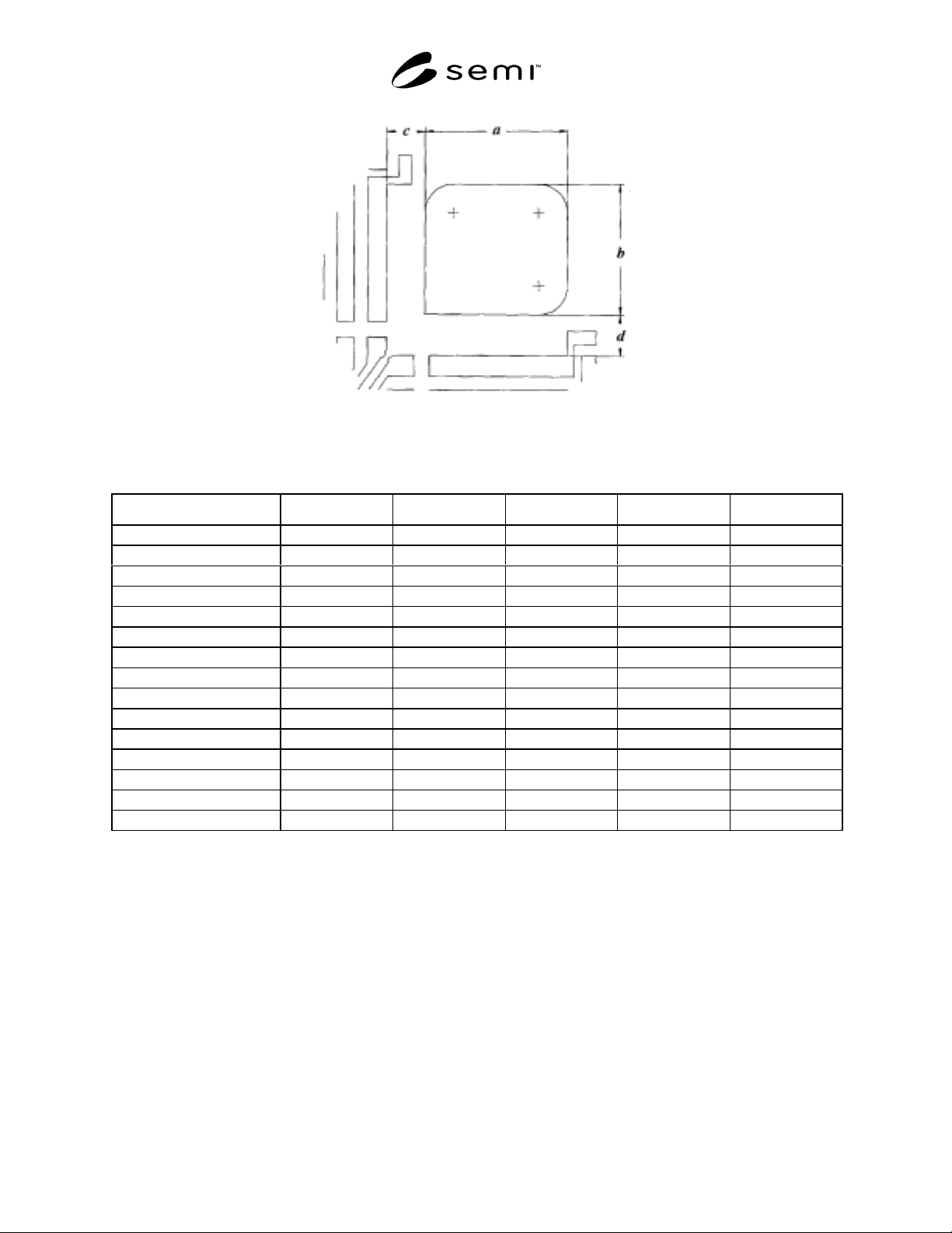
Detail A
Corner Relief Hole (Optional)
Table 2 Leadframe Standard Dimensions
LEADS PKG. BODY a b c d
44 10 × 10 4.200 3.800 1.170 1.170
52 10 × 10 4.200 3.800 1.170 1.170
52 14 × 14 3.735 3.00 0.995 1.075
64 14 × 14 3.735 3.00 0.995 1.075
80 14 × 14 3.735 3.00 0.995 1.075
64 14 × 40 3.735 3.400 0.995 1.075
80 14 × 20 3.735 3.400 0.995 1.075
100 14 × 20 3.735 3.400 0.995 1.075
120 28 × 28 6.600 8.840 1.610 1.610
128 28 × 28 6.600 8.840 1.610 1.610
144 28 × 28 6.600 8.840 1.610 1.610
160 28 × 28 6.600 8.840 1.610 1.610
184 32 × 32 6.600 8.840 1.610 1.610
196 28 × 40 6.600 8.840 1.610 1.610
232 40 × 40 6.600 8.840 1.610 1.610
NOTICE: These standards do not purport to address safety issues, if any, associated with their use. It is the
responsibility of the user of these standards to establish appropriate safety and health practices and determine the
applicability of regulatory limitations prior to use. SEMI makes no warranties or representations as to the suitability
of the standards set forth herein for any particular application. The determination of the suitability of the standard is
solely the responsibility of the user. Users are cautioned to refer to manufacturer’s instructions, product labels,
product data sheets, and other relevant literature respecting any materials mentioned herein. These standards are
subject to change without notice.
The user’s attention is called to the possibility that compliance with this standard may require use of copyrighted
material or of an invention covered by patent rights. By publication of this standard, SEMI takes no position
respecting the validity of any patent rights or copyrights asserted in connection with any item mentioned in this
standard. Users of this standard are expressly advised that determination of any such patent rights or copyrights, and
the risk of infringement of such rights, are entirely their responsibility.
Copyright by SEMI® (Semiconductor Equipment and Materials
International), 3081 Zanker Road, San Jose, CA 95134. Reproduction o
f
the contents in whole or in part is forbidden without express written
consent of SEMI.

SEMI G52-90 © SEMI 1990, 2004 1
SEMI G52-90 (Reapproved 1104)
STANDARD TEST METHOD FOR MEASUREMENT OF IONIC
CONTAMINATION ON SEMICONDUCTOR LEADFRAMES (PROPOSED)
This test method was technically approved by the Global Assembly & Packaging Committee and is the direct
responsibility of the Japanese Packaging Committee. Current edition approved by the Japanese Regional
Standards Committee on July 23, 2004. Initially available at www.semi.org September 2004; to be published
November 2004. Originally published in 1990.
NOTE 1: Japan, Europe, and US task forces are planning to
develop test methods which will address the different levels
of ionic contamination on leadframes.
1 Scope
1.1 This standard describes the procedure to determine
ionic contamination on leadframes using a water
extraction method. The method is sensitive to Na
+
,
NH
4
+
, K
+
, Cl
, NO
3
-
, Br
, SO
4
2
, PO
4
3
.
NOTICE: This standard does not purport to address
safety issues, if any, associated with its use. It is the
responsibility of the users of this standard to establish
appropriate safety and health practices and determine
the applicability of regulatory or other limitations prior
to use.
2 Referenced Standards
2.1 ASTM Specifications
1
D 1193 — Specification for Reagent Water
D 4327 — Anions in Water by Ion Chromatography
NOTICE: Unless otherwise indicated, all documents
cited shall be the latest published versions.
3 Summary of Method
3.1 Ionic contamination is extracted in water at > 95°C
for 30 ± 2 minutes. The contamination is quantitatively
analyzed by ion type using Ion Chromatography and the
result is presented as nanograms/unit area.
4 Significance
4.1 Contamination on leadframes can contribute to
semiconductor device reliability problems. This method
may be used by lead frame manufacturers at outgoing
inspection and by users at incoming inspection.
Correlation of device reliability with contamination
levels may lead to improved leadframe cleaning
processes.
1 American Society for Testing and Materials, 100 Barr Harbor
Drive, West Conshohocken, Pennsylvania 19428-2959, USA.
Telephone: 610.832.9585, Fax: 610.832.9555, Website:
www.astm.org
5 Terminology
5.1 Definitions
5.1.1 eluent — the solvent used to carry the extracted
ions through the ion exchange chromatograph.
5.1.2 regenerant — a chemical solution containing the
ions originally present in the chromatograph column
prior to a test run and used to prepare the column for a
new test.
5.1.3 retention time — the time required for a
particular ion type to pass from the injection port to the
detector. Retention time is characteristically different
for each ion type.
5.1.4 standard solution — a solution containing a
known concentration of the ion to be measured and
used to calibrate the chromatograph.
6 Equipment
6.1 Ion Chromatograph for Anion and Cation Analysis
— This equipment is to consist of a concentration
pump, guard column, separator column, and a detector
module consisting of a suppressor device to reduce the
background eluent conductivity to a low level and a
conductivity cell. The minimum sensitivity of the
chromatograph for each ion type is defined in Table 1.
6.2 Chart Recorder
6.3 Ion Extraction Vessels — Polypropylene or teflon
containers with sealing caps, or polypropylene/
polyethylene double layered bags.
NOTE 2: The contamination level of these vessels must be
less than one-fifth (1/5) of the expected contamination level
on the leadframes when measured in a control test.
6.4 Hot Bar Bag Sealer
6.5 Water Bath — 300 mmL × 300 mmW × 200 mmH,
filled with DI water, and capable of holding 95°C.
6.6 Volumetric Dispenser (e.g., Pipettes) — 10 ml and
100 ml capacity.
6.7 Quartz Flasks and Pipettes for Cation Standard
Solutions — 100, 250, 500, and 1000 ml capacity
(flasks); 1, 10, and 25 ml capacity (pipettes).