semi合集-English.pdf - 第6033页
SEMI G3-90 © SEMI 1 980, 199 6 5 3. Centrifuge — MIL-STD-883, Method 2001.2, Condition E 4. Mechanical Shock — MIL -STD-883, Met hod 2002.2, Con d ition B 9.2.6 Seque nce of Events and I ncomi n g Testing — During incomi…

SEMI G3-90 © SEMI 1980, 1996 4
7.2.2.2 Wire Bond Finger Pullback — A 0.010"
(0.254 mm) maximum from the cavity edge and the
minimum exposed wire bond lead length must meet the
dimension on the procurement drawing or specification.
7.2.2.3 Wire Bond Finger Rundown — Not to exceed
25% of the ceramic layer thickness or 0.005" (0.127
mm), whichever is the smaller.
7.3 Lead Attachment
7.3.1 Voids in Braze
7.3.1.1 Gold Plated Leadframes — 75% of the braze
fillet will be void free.
7.3.1.2 Nickel or Bare Leadframes — 75% of the
braze fillet will be void free.
7.3.2 Lead Alignment
7.3.2.1 Misalignment Leads to Braze Pads — The
leads shall not overhang the braze pads by more than
25% of the measured paddle width nor reduce the
clearance between adjacent pad or lead to less than 50%
of the clearance between adjacent metallizations.
7.3.2.2 Lead Offset — Lead centerlines must be
aligned to within 0.015" (0.381 mm) relative to the
position of the leads on the opposite side of the
package.
7.3.2.3 Lead-to-Lead Alignment — 0.010" ± 0.010"
(0.254 mm ± 0.254 mm) measured at the base of the
ceramic on the same side.
8 Sampling
Sampling sizes must meet the requirements of MIL-
STD-105; although single, double, or multiple samples
may be used.
9 Test Methods
9.1 Mechanical, Electrical and Thermal Test Methods
9.1.1 Gold Plating Quality
9.1.1.1 Purity and adhesion of the gold plated package
shall be tested by placing parts on a calibrated heater
block at:
Condition A — 450°C ± 10°C for two minutes in air, or
Condition B — 470°C ± 10°C for one minute in
nitrogen.
9.1.1.2 After cooling at room temperature the
packages will be visually examined for the following
criteria:
9.1.1.2.1 Blisters on the leadframe are acceptable only
on the tie bar (that portion removed during trim).
Blisters on the bonding fingers shall not exceed 0.003"
(0.076 mm) diameter with a maximum of 1 blister per
finger and 5 blisters per package of any size. Blisters on
the seal ring shall not exceed 0.005" (0.127 mm)
diameter. Blisters on the die attach pad shall not exceed
0.010" (0.254 mm) diameter with a maximum of 5
blisters per package greater than 0.005" (0.127 mm)
diameter.
9.1.1.2.2 Slight discoloration of the gold at the die
attach pad edges up to 0.025" (0.635 mm) from the
cavity walls is acceptable. Discoloration of the bonding
fingers, seal ring surface or external leads is not
acceptable.
9.1.1.2.3 There shall be no flaking or peeling of the
package plating when viewed at 15× magnification.
9.1.1.2.4 Superficial stains left during drying or prior
operations is not cause for rejection.
9.1.2 Lead Pull — Four pounds (1.8 kg) minimum at a
45° angle from the lead’s original plane.
9.1.3 Lead Fatigue — Test per MIL-STD-883,
Method 2004.2, Test Condition B2, Section 3.2.
9.1.4 Thermal Characteristics — Test per MIL-STD-
883, Method 1012, Test Conditions A, B, C, D, and E.
9.2 Functional Test Methods
9.2.1 Die Attach Quality — Perform destructive die
shear test post environmental testing per MIL-STD-
883, Method 2019.1, Section 3.2C.
9.2.2 Wire Bond Quality — Perform minimum pre-
seal and post-seal bond strength test per MIL-STD-883,
Method 2011.2, Test Condition D. Reject for bonds
which cause plating to lift from the base metal of the
die attach surface or bonding fingers.
9.2.3 Solderability — Test per MIL-STD-883, Method
2003.2.
9.2.4 Insulation Resistance — Test per MIL-STD-883,
Method 1003.
9.2.5 Hermetic and Environmental Testing
9.2.5.1 The hermetic integrity of the package must be
maintained after all environmental testing. Hermetic
checks shall comply with MIL-STD-883, Method
1014.3, Test Condition A
1
or B and C.
9.2.5.2 Environmental testing shall include, but not be
limited to, the following:
1. Temperature Cycle — MIL-STD-883, Method
1010.2 Condition C
2. Thermal Shock — MIL-STD-883, Method 1011.2,
Condition C
SEMI G3-90 © SEMI 1980, 19965
3. Centrifuge — MIL-STD-883, Method 2001.2,
Condition E
4. Mechanical Shock — MIL-STD-883, Method
2002.2, Condition B
9.2.6 Sequence of Events and Incoming Testing —
During incoming inspection the sequence of testing
shall be:
1. Die Attach
2. Wire Bond
3. Pre-Seal Bond Pull
4. Seal
5. Environmental Test
6. Fine Leak
7. Gross Leak
8. Trim
9. Post-Seal Bond Pull
10.Radiography
11. Die Shear
12. Solderability
NOTE: An initial vendor qualification on the thermal and
electrical characteristics of the package may be performed.
The characteristics tested will be:
1. Insulation Resistance — MIL-STD-883, Method
1003, Test Condition D
2. Thermal Dissipation — MIL-STD-883, Method
1012
10 Packaging and Marking
10.1 Packaging — Containers selected shall be strong
enough and suitably designed to provide maximum
protection against crushing, spillage, and other forms of
damage to the container or its contents. Containers shall
afford protection of the contents to contamination from
exposure to excessive moisture or oxidation by gases.
Packaging materials shall be so selected to prevent any
contamination of the ceramic component parts with
paper fibers or organic particles.
10.2 Marking — The outer containers shall be clearly
marked to identify the user stock number, user purchase
order number, drawing number, quantity, and vendor
lot number.
11 Product Design
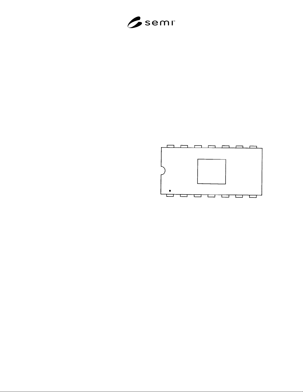
11.1 Leadframe Paddle Width and Standoff — (See
Figure 5.)
NOTE: A geometric symbol adjacent to an identifying lead
number 1 shall be considered appropriate for packages with
all leads isolated from the die attach.
NOTE: Lead number 14 is common to die attach surface and
is identified by placing this number where lead number 1 is
located.
11.1.1 Leadframe paddle width shall be 1.14 mm
(0.045") ± 0.178 mm (0.007").
11.1.2 Standoff shall be 1.02 mm ± 0.254 mm (0.040"
± 0.010").
11.1.3 Hole Diameter shall be 0.032" – 0.033" (0.813
mm – 0.838 mm).
11.2 Substrate/Terminal Commonality on Sidebrazed
Laminate Packages — If no leads are common to the
die attach surface, the lead one identification shall be a
geometric symbol (Figure 6).
Figure 6
Lead Identification
SEMI G3-90 © SEMI 1980, 1996 6
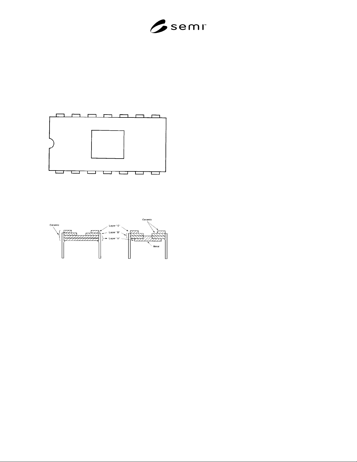
Layers shall be designated by letter beginning with “A”
as that layer nearest terminal insertion plane. Layers,
regardless of function, shall be designated by
succeeding letters, (B, C, D, etc.) as being progressively
remote from the terminal insertion plane.
Should any lead be common to the die attach surface,
that lead number will serve both as lead one
identificationand as an indicator as to the lead that is
common to the die attach surface (Figure 7).
14
Figure 7
Lead Identification
11.3 Sidebraze Ceramic Package Layer Design —
(See Figure 8).
Figure 8
Layer Designation