semi合集-English.pdf - 第7228页
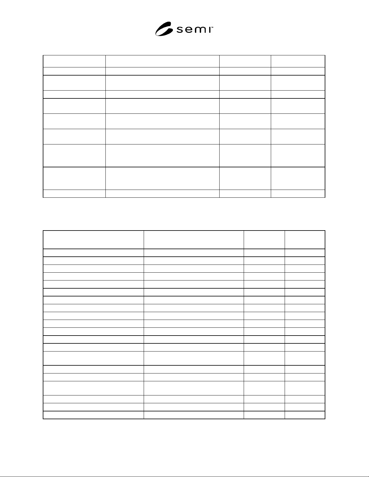
SEMI MF154-0305 © SEMI 2003, 2005 2 Table 1 Wafer Structural Defects #1, #2, #3 Defect Common Synonyms and Ac ronyms Illustrating Figure ( s ) Relevant Standard ( s ) Dislocation etch pit etch pit, pit 1-5 SEMI MF1725 Ep…

SEMI MF154-0305 © SEMI 2003, 2005 1
SEMI MF154-0305
GUIDE FOR IDENTIFICATION OF STRUCTURES AND
CONTAMINANTS SEEN ON SPECULAR SILICON SURFACES
This guide was technically approved by the Global Silicon Wafer Committee and is the direct responsibility
of the North American Silicon Wafer Committee. Current edition approved for publication by the North
American Regional Standards Committee on December 10, 2004. Initially available at
www.semi.org
January 2005; to be published March 2005. Original edition published by ASTM International as ASTM F
154-72T. Last previous edition SEMI MF154-02.
1 Purpose
1.1 The purpose of this guide is to list, illustrate, and provide reference for various characteristic features and
contaminants that are seen on highly specular silicon wafers.
1.2 Ambiguities and uncertainties regarding surface defects may be resolved by reference to this guide.
1.3 There is close alignment between this guide and common specifications used for the purchase of silicon wafers.
2 Scope
2.1 This guide contains a compilation of the most commonly observed singularly discernible structures on specular
silicon surfaces.
2.2 Recommended practices for delineation and observation of these artifacts are referenced. The artifacts described
in this guide are intended to parallel and support the content of the specification form for order entry in SEMI M18.
2.3 These artifacts and common synonyms are arranged alphabetically in Tables 1 and 2 and illustrated in Figures 1
through 68.
NOTICE: This standard does not purport to address safety issues, if any, associated with its use. It is the
responsibility of the user of this standard to establish appropriate safety and health guides and determine the
applicability of regulatory or other limitations prior to use.
3 Limitations
3.1 Defects, structures, features, or artifacts revealed or enhanced by the referenced methods and exhibited in this
guide must be carefully interpreted. Unless utmost care is exercised, the identification of the structure may be
ambiguous.
4 Referenced Standards
4.1 SEMI Standards
SEMI M18 — Format for Silicon Wafer Specification Form for Order Entry
SEMI M59 — Terminology for Silicon Technology
SEMI MF523 — Practice for Unaided Visual Inspection of Polished Silicon Wafer Surfaces
SEMI MF1725 — Guide for Analysis of Crystallographic Perfection of Silicon Ingots
SEMI MF1726 — Guide for Analysis of Crystallographic Perfection of Silicon Wafers
SEMI MF1727 — Practice for Detection of Oxidation Induced Defects in Polished Silicon Wafers
SEMI MF1809 — Guide for Selection and Use of Etching Solutions to Delineate Structural Defects in Silicon
SEMI MF1810 — Test Method for Counting Preferentially Etched or Decorated Surface Defects in Silicon Wafers
NOTICE: Unless otherwise indicated, all documents cited shall be the latest published versions.
SEMI MF154-0305 © SEMI 2003, 2005 2
Table 1 Wafer Structural Defects
#1, #2, #3
Defect Common Synonyms and Acronyms Illustrating Figure(s) Relevant Standard(s)
Dislocation etch pit etch pit, pit 1-5 SEMI MF1725
Epitaxial stacking fault epi stacking fault, (ESF)
Epitaxial growth hillock
6-10 SEMI MF1726
Lineage Grain Boundary 11 SEMI MF1725
Oxidation induced stacking
fault
oxidation stacking fault, (OSF), oxidation induced
stacking fault (OISF)
12-18 SEMI MF1727
SEMI MF1809
Oxide precipitates bulk micro-defect, (BMD), bulk precipitate 19 SEMI MF1727
SEMI MF1809
Shallow pits S-pit, saucer pit 20-21 SEMI MF1727
SEMI MF1809
Slip slip lines 22-25 SEMI MF1725
SEMI MF1727
SEMI MF1809
Swirl 26-27 SEMI MF1725
SEMI MF1727
SEMI MF1809
Twin twin lamella, twin line 28-30 SEMI MF1725
#1
Magnifications given in the attached illustrations are for an original frame size of 50 mm × 50 mm, except as noted.
#2
Unless otherwise noted, all attached figures illustrate polished silicon wafer surfaces.
#3
Unless otherwise noted, all attached figures with magnified images were created using interference contrast microscope equipment.
Table 2 Polished Surface Visual Characteristics
Defect Common Synonyms and Acronyms
Illustrating
Figure(s)
Relevant
Standard
Area contamination Contamination, foreign matter, residue 31-32 SEMI MF523
Crack Cleavage, fracture 33-38 SEMI MF523
Crater Slurry ring 39 SEMI MF523
Crow's feet Contact damage 40 SEMI MF523
Dimple Depression 41-42 SEMI MF523
Dopant striation ring Striation 43 SEMI MF523
Edge chip Chip 44-47 SEMI MF523
Edge crack Crack 48 SEMI MF523
Edge crown 49 SEMI MF523
Epitaxial large point defect large light point defect, (LLPD), spike 50 SEMI MF523
Foreign matter Contamination, residue 51-52 SEMI MF523
Groove Polished over scratch, microscratch 53-54 SEMI MF523
Haze 55-56 SEMI MF523
Localized light scatterers (particle
contamination)
large light scatterers, (LLS) 57-58 SEMI MF523
Mound 59 SEMI MF523
Orange peel Roughness 60 SEMI MF523
Pits Air pocket, hole, crystal originated pit,
(COP) insufficient polish
61-63 SEMI MF523
Saw mark 64 SEMI MF523
Scratches Handling damage 65-67 SEMI MF523
Stain 68 SEMI MF523

SEMI MF154-0305 © SEMI 2003, 2005 3
5 Terminology
5.1 Terms related to silicon technology, including the features and contaminants discussed in this guide, are defined
in SEMI M59.
6 Procedure
6.1 Procedures for examining silicon wafers for the features and contaminants discussed in this guide are covered in
SEMI MF523, SEMI MF1725, SEMI MF1726, SEMI MF1727, SEMI MF1809, and SEMI MF1810.
7 Keywords
contaminant; defects; dislocation; epitaxial; fracture; preferential etch; scratch; shallow pit; silicon; slip; stacking
fault
Figure 1
Dislocation Etch Pits on (111)
Silicon, Following 3-Min Sirtl
Etch, Magnification 110×
Figure 2
Dislocation Etch Pits on (110)
Silicon, Following 5-Min Wright
Etch, Magnification 110×
Figure 3
Dislocation Etch Pits on (100)
Silicon Following Schimmel (B)
Preferential Etch, Magnification
320×
Figure 4
Dislocation Etch Pits on (100)
Silicon Following Sirtl Etch,
Magnification 400×
Figure 5
Dislocation Etch Pits on (100)
Silicon Following 5-Min Wright
Etch, Magnification 200×
Figure 6
Epitaxial Stacking Faults on
(111) Following 4.2 m Dash etch,
Size Dependent Upon EPI
Thickness