semi合集-English.pdf - 第1052页
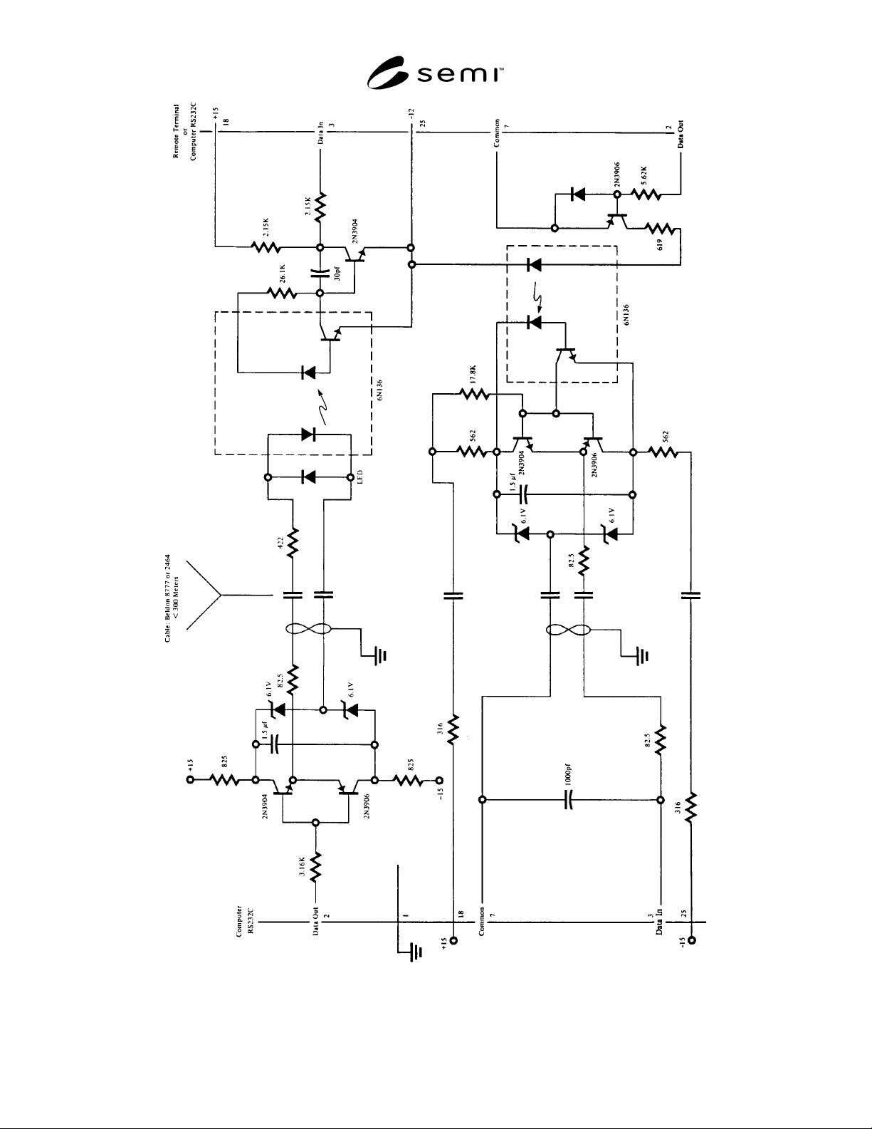
SEMI E4-0699 © SE MI 1980, 1999 14 Figure R1-1 RS-232 Is olation Examp le

SEMI E4-0699 © SEMI 1980, 199913
RELATED INFORMATION
NOTICE — The material contained in this Related
Information is not an official part of SEMI E4 (SECS-I)
and is not intended to modify or supercede the official
standard. Rather, this information describes possible
methods for implementing the protocol described by the
standard and are included as reference material. The
standard should be referred to in all cases. SEMI makes
no warranties or representations as to the suitability of
the material set forth herein for any particular
application. The determination of the suitability of the
material is solely the responsibility of the user.
R1-1 Miscellaneous Notes on SECS-I
R1-1.1 Layered Protocol (see Section 1.3.1) — The
lnternational Standards Organization (ISO) has
published a model for Open Systems lnterconnection
(OSI). The SECS-I protocol both predates the ISO/OSI
model and is not a true "open system" and, therefore,
does not correspond exactly to the ISO/OSI model. The
SECS-I protocol is a communications interface rather
than a network protocol. However, the SECS-I levels
can be roughly compared to layers 1 through part of
layer 5 of the ISO/OSI model. ISO/OSI layer 1, the
physical link layer, corresponds to the SECS-I physical
link. ISO/OSI layer 2, the data link layer, corresponds
to the SECS-I block transfer protocol. lSO/OSI layer 3,
the network layer, is a function of the host and is not
defined in SECS-I beyond the provision for a bi-
directional flow (see Section 6.2). Similarly, network
management is assumed to be the responsbility of the
host. ISO/OSI layer 4, the transport layer, is covered by
the SECS-I block transfer protocol, duplicate block
detection, and the message protocol. ISO/OSI layer 5,
the session layer, is partially covered by the SECS-I
message protocol.
R1-1.2 Single Timer for T1 and T2 (see Section 5.3) —
A single timer can be used for both the inter-character
timer and the protocol timer, since both are the time
between receiving successive characters and both limits
are never in effect at the same time.
R1-1.3 Stalling (see Section 5.8.2) — The line control
portion of the block transfer protocol has the ability to
delay the acceptance of a data block by not responding
with an EOT immediately after receiving an ENQ. Such
an action by the receiver is called "Stalling." If the
delay exceeds the sender's T2 value, the sender will
send another ENQ. This can be continued depending
upon the sender's setting of T2 and RTY. Such a delay
should be an occasional convenience to accommodate
random short delays in the receiver's ability to accept a
new block and should not be counted upon routinely to
make up for poor response. In particular, the block
transfer protocol should probably have at least two
buffers available for storing incoming blocks. This
allows one block to be inspected by the message
protocol while the next block is being received, thus
allowing a reasonably continuous reception of data. If
both buffers are full and the message protocol is slow in
freeing the buffer for the block transfer protocol, then
the block transfer protocol will start stalling the sender.
If the sender is stalled long enough, it will declare a
send error, which is probably the correct thing to do.
The sender cannot distinguish between a reluctance to
receive and failure in the communications. In either
situation, since no block gets through in a
predetermined time limit, the communications link is
effectively broken. Arbitrarily long delays are not
acceptable in SECS-I.
R1-1.4 Determining the Cause of an NAK (see Section
5.8.5) —The block transfer protocol does not include a
way for a sender to determine the cause of an NAK. If
such information is useful for application purposes, it
must be collected at the receiving end.
R1-1.5 Master Sending a Long Message (see Section
5.8) —When the master is sending a long message, the
slave may be unable to send a block, which may result
in timeouts. It is good practice for the master to
introduce enough delay between blocks so that the slave
has a chance to send a block every few seconds.
R1-1.6 Device Identification (see Section 6.3) —
Although the 15 bits of the device ID can identify
32,767 different devices, the host may find it more
convenient to use the upper seven bits to identify the
type of device such as a spinner or diffusion furnace,
and to use the lower eight bits to identify the specific
device of that type.
R1-1.7 Sending Multiple Open Messages (see Section
7.2.4) —The message protocol algorithms defined in
the standard are capable of inter-leaving the blocks of
any number of open multi-block messages. Since the
receiving protocol is sensitive to the time between
blocks of each message being received, it is proper
procedure for the sending algorithm to alternate
between messages when sending blocks from
interleaved multi-block messages.
R1-1.8 Single Timer for T3 and T4 (see Sections 7.3.2
and 7.4.3) — For a given transaction, a single timer can
be used for both the inter-block timer and the reply
timer, since both are the time between receiving
successive blocks of a message, and both limits are
never in effect at the same time.
SEMI E4-0699 © SEMI 1980, 1999 14
Figure R1-1
RS-232 Isolation Example
SEMI E4-0699 © SEMI 1980, 199915
R1-2 Isolation
R1-2.1 As mentioned in Section 3.4, the standard RS-
232-C line does not provide isolation between the
grounds of remote equipment and a central computer. It
is often desirable to provide isolation to minimize
communications errors and to protect equipment. The
following example is provided here to illustrate how
such an isolation might be provided between two
devices using RS-232-C, while at the same time
providing the capability to drive longer lines. This
description is provided for information only and is not
part of the standard.
R1-2.2 Figure R1-1 illustrates a possible circuit for
isolation which provides line isolation and line driving
capability. The two wires used to provide power to the
remote isolator are required since any local power
supply would have the same isolation problems as the
data wires. The power wires also eliminate extra
supplies at every terminal or remote device. There are
many other possible circuits. This example has been
used successfully and works quite well at 9600 baud for
lines less than 300 meters and illustrates the use of the
voltages on pins 18 and 25 as mentioned in 3.2.4.
R1-3 Examples of Block Transfer Protocol
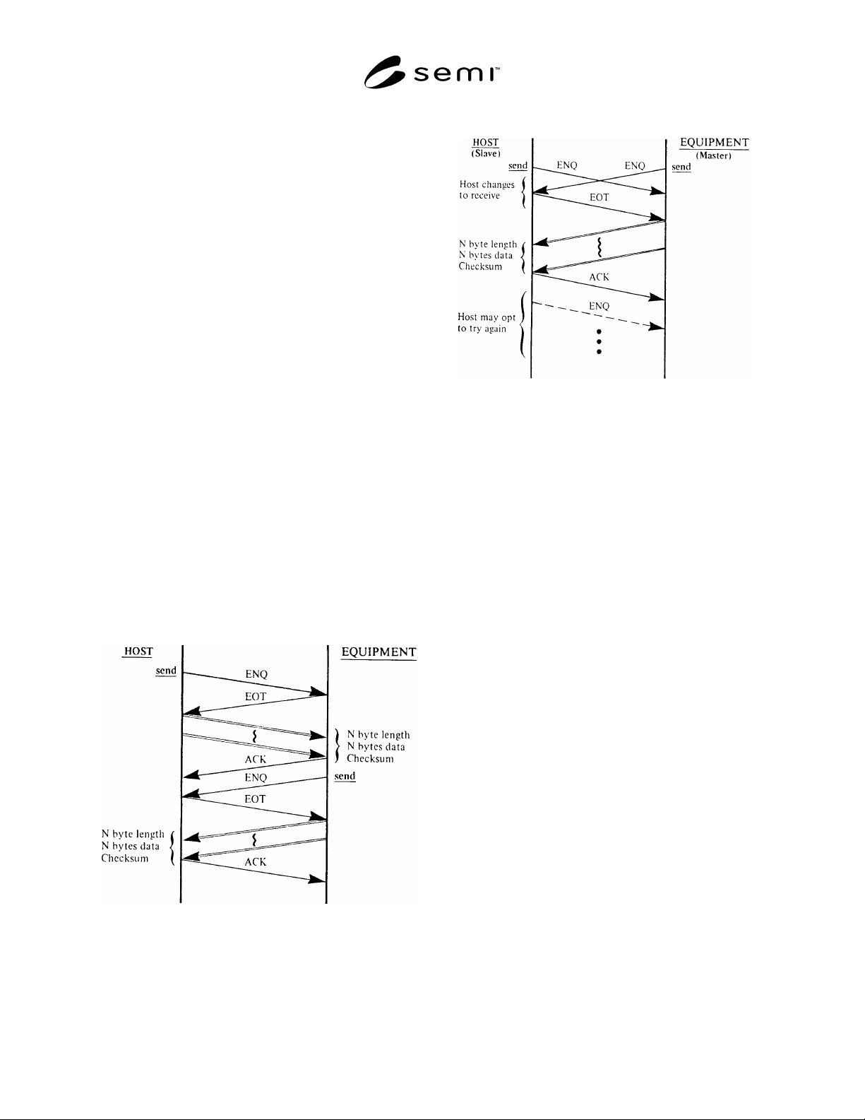
R1-3.1 Figures R1-2 and R1-3 illustrate some simple
message interactions between the host and the
equipment. Figure R1-2 shows the handshake sequence
possible to acquire the status of the equipment. Fig-ure
R1-3 shows the sequence of events when both the host
and the equipment try to send at the same time.
Figure R1-2
Ask for Status
Figure R1-3
Contention Resolution
R1-4 Use of Buffers in the Block Transfer
Protocol
R1-4.1 In the flow chart of the Block Transfer Protocol
(Figure 2), the flow chart entry "LISTEN" implies that
characters are recognized after entering the given state
and not before. If the particular implementation uses
buffers and stores all of the characters received before
the "LISTEN" state is achieved, care must be taken in
the proper handling of the data in the buffer to avoid
problems due to "timing windows" between sending
and receiving.
R1-4.2 If the buffer is cleared before sending the last
character prior to the "LISTEN" (last checksum byte in
sending a message, ENQ or EOT in line control), there
is still a time, albeit small, where spurious characters
could be received into the buffer.
R1-4.2.1 In addition, during the sending of the
message, a delay between the checksum bytes while the
buffer is cleared may cause an inter-character timeout
by the receiver. If the buffer is cleared after the last
character sent before the "LISTEN," there is a
possibility that the desired character will be cleared
from the buffer.
R1-4.3 One solution is to look at the buffer after
entering the "LISTEN" state and examine the last
character in the buffer, if any are there. This works
while listening for an EOT after sending an ENQ. In the
case where the sender is listening for an ACK after
sending the second checksum byte, it is possible that
the receiver also has a block to send, and follows the