semi合集-English.pdf - 第6340页
SEMI G67-0996 © SEMI 1996, 2004 2 10.2 Allow the clean bench to come to equilibrium and perform a backgr ound particle count. NOTE 1: Between each test, allow th e clean bench to return to a stable background particle co…
SEMI G67-0996 © SEMI 1996, 2004 1
SEMI G67-0996 (Reapproved 1104)
TEST METHOD FOR THE MEASUREMENT OF PARTICLE
GENERATION FROM SHEET MATERIALS
This test method was technically reapproved by the Global Assembly & Packaging Committee and is the
direct responsibility of the Japanese Packaging Committee. Current edition approved by the Japanese
Regional Standards Committee on July 23, 2004. Initially available at www.semi.org September 2004; to be
published November 2004. Originally published September 1996.
1 Purpose
1.1 This test method describes a procedure to measure
particles on sheet materials.
2 Scope
2.1 The method described may be used for the
measurement of particles on items such as:
• Leadframe Interleaves,
• Cleanroom Paper, and
• Packing Material.
2.2 The procedures may be used by the material
manufacturer for quality control or by a customer at
incoming inspection.
NOTICE: This standard does not purport to address
safety issues, if any, associated with its use. It is the
responsibility of the users of this standard to establish
appropriate safety and health practices and determine
the applicability of regulatory or other limitations prior
to use.
3 Referenced Standards
3.1 None.
NOTICE: Unless otherwise indicated, all documents
cited shall be the latest published versions.
4 Terminology
4.1 None.
5 Summary of Method
5.1 The method is based on measuring a background
particle count in a clean enclosure and then measuring
the increased particle count when items under test are
submitted to handling operations likely to generate
particles.
6 Interference
6.1 Care must be taken to avoid contaminating the
clean bench when sheet materials are placed inside. All
external packaging material shall be removed and the
internal packaging shall be cleaned by appropriate
means prior to placing inside the bench.
6.2 A method of cutting the specimens to size, if
performed, must not add to, or detract from, the
contamination levels on the sheet materials.
6.3 Care must be taken to avoid contaminating the
specimens from the human body and clothes when the
sheet materials are prepared for the test method.
7 Equipment
7.1 Particle Counter and Recorder
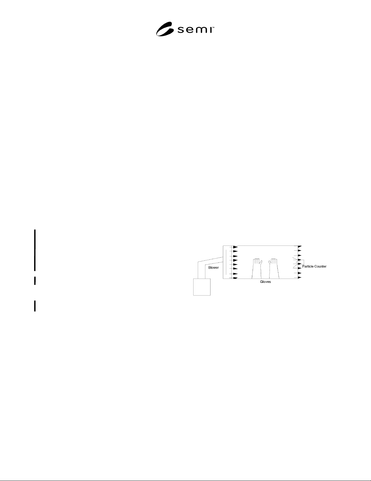
7.2 Clean Bench with Full Gloves and a Dust Particle
Measurement Port — See Figure 1.
7.2.1 Air flow speed in the clean bench should be 0.6
m/sec.
Figure 1
Clean Bench Configuration
8 Sampling
8.1 Sampling plans shall be agreed between user and
supplier.
9 Test Specimen
9.1 Specimen size shall be agreed between user and
supplier. It is recommended that a 152.4 mm × 203.2
mm (6 × 8 inches) test piece be used.
10 Equipment Set-Up
10.1 The particle counter shall be set up with the probe
in the clean bench. Calibrate the counter in accordance
with the equipment manufacturer's instructions.

SEMI G67-0996 © SEMI 1996, 2004 2
10.2 Allow the clean bench to come to equilibrium and
perform a background particle count.
NOTE 1: Between each test, allow the clean bench to return
to a stable background particle count before proceeding with
the next test.
NOTE 2: After several thousand particles have been
measured, the clean bench must be cleaned before making the
next measurement.
11 Test Procedure
11.1 Place the items to be tested in the clean bench and
allow the clean bench to return to a stable background
level for particle count.
11.2 Crumpling Test
11.2.1 Crumple a test specimen in gloved hands at the
rate of one (1) crumple every fifteen (15) seconds and
record the maximum particle count.
11.2.2 Record the maximum particle count and the
initial background count.
11.3 Friction Test
11.3.1 Place two sheets of the material to be tested face
to face and rub together three (3) times in ten (10)
seconds.
11.3.2 Record the maximum particle count and the
initial background count.
11.4 Tearing and Crumpling Test
11.4.1 Tear a sheet into five (5) pieces at the rate of
one (1) tear every five (5) seconds. Crumple the pieces
in gloved hands at the rate of one (1) crumple every
fifteen (15) seconds.
11.4.2 Record the maximum particle count and the
initial background count.
12 Calculations and Reporting Results
12.1 For each measurement and test method type,
calculate the particle count on the material under test as
follows:
• Particle Count (no./m
3
) = (Measured Count from
each test) - (Background Count)
12.2 Average the results for each test type.
13 Report
The test report shall include the following items:
• Material Designation under Test,
• Manufacturer,
• Shipping Lot Number,
• Test Date,
• Test Conditions — temperature, humidity in the
clean bench,
• Particle Counter Sensitivity,
• Test Time, and
•
Results for Each Test Type in particles/m
3
.
NOTE 3: If the test is performed by the manufacturer, some
of these items may be replaced by in-house requirements such
as manufacturer lot number.
NOTICE: SEMI makes no warranties or
representations as to the suitability of the standards set
forth herein for any particular application. The
determination of the suitability of the standard is solely
the responsibility of the user. Users are cautioned to
refer to manufacturer's instructions, product labels,
product data sheets, and other relevant literature,
respecting any materials or equipment mentioned
herein. These standards are subject to change without
notice.
By publication of this standard, Semiconductor
Equipment and Materials International (SEMI) takes no
position respecting the validity of any patent rights or
copyrights asserted in connection with any items
mentioned in this standard. Users of this standard are
expressly advised that determination of any such patent
rights or copyrights, and the risk of infringement of
such rights are entirely their own responsibility.
Copyright by SEMI® (Semiconductor Equipment and Materials
International), 3081 Zanker Road, San Jose, CA 95134. Reproduction o
f
the contents in whole or in part is forbidden without express written
consent of SEMI.

1 SEMI G68-0996 © SEMI 1996, 2004
SEMI G68-0996 (Reapproved 1104)
TEST METHOD FOR JUNCTION-TO-CASE THERMAL RESISTANCE
MEASUREMENTS IN AIR ENVIRONMENT FOR SEMICONDUCTOR
PACKAGES
This test method was technically approved by the Global Assembly & Packaging Committee and is the direct
responsibility of the Japanese Packaging Committee. Current edition approved by the Japanese Regional
Standards Committee on July 23, 2004. Initially available at www.semi.org September 2004; to be published
November 2004. Originally published in 1996.
1 Purpose
1.1 The purpose of this test is to determine the thermal
resistance of semiconductor packages using thermal test
chips. This test method deals with junction-to-case
measurements of thermal resistance in air environment.
2 Scope
2.1 The results of this test method are used to obtain
the junction temperature.
2.2 The measurement results are usually different from
the results obtained by testing in the fluid bath
environment described in SEMI G30 and SEMI G43.
2.3 This test method uses SI units.
NOTICE: This standard does not purport to address
safety issues, if any, associated with its use. It is the
responsibility of the users of this standard to establish
appropriate safety and health practices and determine
the applicability of regulatory or other limitations prior
to use.
3 Limitation
3.1 This method applies only to packages whose
surface is wide enough to place a thermocouple.
4 Referenced Standards
4.1 SEMI Standards
SEMI G30 — Test Method for Junction-to-Case
Thermal Resistance Measurements of Ceramic
Packages
SEMI G32 — Guideline for Unencapsulated Thermal
Test Chip
SEMI G38 — Test Method for Still- and Forced-Air
Junction-to-Ambient Thermal Resistance
Measurements of Integrated Circuit Packages
SEMI G42 — Specification for Thermal Test Board
Standardization for Measuring Junction-to-Ambient
Thermal Resistance of Semiconductor Packages
SEMI G43 — Test Method for Junction-to-Case
Thermal Resistance Measurements of Molded Plastic
Packages
NOTICE: Unless otherwise indicated, all documents
cited shall be the latest published versions.
5 Terminology
5.1 Definitions
5.1.1 The following definitions and symbols shall
apply to this test:
5.1.2 case top temperature measured in air
environment, T
t
— in °C, is the temperature at the
specified accessible reference point on the package in
measured in air environment.
NOTE 1: T
C
defined in SEMI G43 is different from T
t
.
5.1.3 junction temperature, T
j
— in °C, is the
temperature of the semiconductor junction on the
microcircuit in which the major part of the heat is
generated.
5.1.4 power dissipation P
H
— in watt, is the heating
power applied to the device causing a junction-to
reference point temperature difference.
5.1.5 thermal resistance measured in air environment,
junction to package surface,
jt
— in °C/watt, is the
temperature difference from the junction to the center
point on the package divided by the power dissipation
P
H
.
6 Summary of Method
6.1 A thermocouple is attached on the surface of the
package on the test board.
6.2 After the chip is heated, the junction temperature is
measured by the diode in the test chip. The surface
temperature is measured in an air environment by the
thermocouple.
6.3 The junction-to-case thermal resistance is
calculated using the case temperature, junction
temperature and power dissipation.