semi合集-English.pdf - 第6050页
SEMI G5-87 © SEMI 1 980, 199 6 2 i. Portion of ext ernal footprin t s connected to die attach area and/or seal ring . j. T erminal #1 position, internal and external. k. Certificatio n (optional). l. Method of test a nd …

SEMI G5-87 © SEMI 1980, 19961
SEMI G5-87
STANDARD FOR CERAMIC CHIP CARRIERS
1 Scope
This specification defines the acceptance criteria for co-
fired, ceramic chip carriers both leaded and lead-less.
2 Applicable Documents
2.1 ANSI Specification
1
S Y 14.5 — Dimensioning and Tolerancing
2.2 Federal Specification
2
QQ-N-290 — Nickel Plating
2.3 JEDEC Specification
3
Pub. No. 95 — Registered and Standard Outline for
Solid State Products
2.4 Military Specifications
4
MIL-STD-105 — Sampling Procedures and Tables for
Inspection by Attributes
MIL-STD-883 — Test Methods and Procedures for
Microelectronics
MIL-STD-7883 — Brazing
MIL-M-38510 — General Specification for
Microcircuits
MIL-STD-45204 — Gold Plating, Electrodeposited
2.5 SEMI Specifications
SEMI G8 — Test Method for Gold Plating Quality
SEMI G25 — Test Method for Measuring the
Resistance of Package Leads
SEMI G6 — Test Method for Seal Ring Flatness
3 Selected Definitions
braze — An alloy with a melting point equal to or
greater than 600°C.
castellation — That series of ribs and metallized
indentations that define edge contact regions (see
Figure 1).
1 ANSI, 1430 Broadway, New York, NY 10018
2 Military Standards, Naval Publications and Form Center, 5801
Tabor Ave., Philadelphia, PA 19120
3 JEDEC, 2001 Eye Street, N.W., Washington, D.C. 20006
4 General Services Administrator, 4th and D Streets, SW, Room
6039, Washington, D.C. 20407
fired — A process or technology to manufacture
products in which the ceramic and refractory
metallization are fired simultaneously.
contact pad — That metallized pattern that provides
mechanical or electrical connection to the external
circuitry.
die attach surface — See Figure 3.
footprint — Contact pad pattern.
layer — A dielectric sheet with or without metallization
that performs a discrete function as a part of the
package.
lead offset — Alignment of leads across the package.
pullback — The linear distance between the edge of the
ceramic and the first measurable metallization and/or
glass interface (see Figures 4 and 5).
rundown — See Figures 4 and 5.
seal-area — A dimensional outline area designated for
either metallization or bare ceramic to provide a surface
area for sealing (see Figure 3).
terminal — Case outline at point of entry or exit of an
electrical contact.
TIR — Total Indicator Reading.
4 Ordering Information
Purchase order for ceramic chip carriers furnished to
this specification shall include the following items:
1. Quantity
2. Drawing — The drawing(s) for ceramic chip
carriers shall specify the following information:
a. Drawing number and revision level.
b. Number of terminals and terminal center line
spacing.
c. Lead material and dimensions.
d. Critical material properties.
e. Type and thickness of plating.
f. Package dimensions per ANSI Y14.5.
g. Internal bonding patterns.
h. Minimum exposed metallized bond finger length
and width.

SEMI G5-87 © SEMI 1980, 1996 2
i. Portion of external footprints connected to die
attach area and/or seal ring.
j. Terminal #1 position, internal and external.
k. Certification (optional).
l. Method of test and measurements.
m. Electrical, mechanical, environmental
requirements.
3. Reference to this specification
4. Any exception to print or specification
5 Dimensions and Permissi ble Variations
5.1 The dimensions of ceramic chip carriers shall
conform to those specified in the customer drawing,
and be within the outline of JEDEC Publication No. 95.
NOTE: A dimensioning scheme and measurement fixture are
under task force review.
5.2 Critical Material Parameters
5.2.1 Ceramic
5.2.1.1 Alumina, content 90% minimum.
5.2.1.2 Color — Dark or white.
5.2.2 Metallization
5.2.2.1 Refractory metallization.
5.2.2.2 Plating (if designated) per MIL-M-38510.
5.2.2.3 Nickel per QQ-N-290
5.2.2.4 Gold per MIL-STD-45204, Type III.
5.2.2.5 Gold Plating Quality see SEMI G8.
5.2.3 Braze per MIL-STD-7883.
5.2.4 Lead per MIL-STD-23011.
5.2.4.1 Iron Nickel Cobalt alloy per MIL-M-38510,
Type A.
5.2.4.2 Iron Nickel alloy per MIL-M-38510, Type B.
6 Functional Testing
The following tests are recommended for functional
evaluation of ceramic chip carriers. (The conditions of
acceptance to be negotiated between the customer and
the vendor.)
6.1 Die Attach
6.2 Pre-Seal Die Shear — (See Section 10.1.6.)
6.3 Wire Bond
6.4 Pre-Seal Bond Pull — (See Section 10.1.7.)
6.5 Seal
6.6 Environmental Test — (See Sections 10.1.1
through 10.1.13.)
6.7 Hermeticity — (See Section 10.1.14) Lid Torque
or Shear (for glass seal parts).
6.8 Post-Seal Bond Pull — (See Section 10.1.7.)
6.9 Post-Seal Die Shear — (See Section 10.1.6.)
7 Incoming Testing
7.1 Visual — (See Section 8.)
7.2 Dimensions
7.3 Functional — (See Section 6.)
7.4 Standard Tests
7.4.1 Electrical — (See SEMI G25.)
7.4.2 Gold Plating Quality — (See SEMI G8.)
7.4.3 Trim
7.4.4 Lead Integrity —(See Section 10.1.15.)
7.4.5 Solderability — (See Section 10.1.16.)
8 Visual
8.1 Applicable Definitions
blister (bubble) ceramic — Any separation within the
ceramic which does not expose underlying ceramic
material.
blister (bubble) metal — Any localized separation
within the metallization or between the metallization
and ceramic which does not expose underlying metal or
ceramic material.
burr — An adherent fragment of excess parent material
at the component edge.
chip — A region of ceramic missing from the surface or
edge of a package which does not go completely
through the package. Chip size is given by its length,
width, and depth from a projection of the design plan-
form (see Figure 2).
crack — A cleavage or fracture, internal or external.
die attach surface — See Figure 3.
discoloration — Any non-uniform color change of the
package plating.
foreign material — An adherent particle other than
parent material of that component.
LSI — Large scale integration.
SEMI G5-87 © SEMI 1980, 19963
void, dielectric — An absence of screen printed
ceramic from a designated area greater than 0.76 mm
(0.003") in diameter.
void, metallization — An absence of refractory
metallization, braze, or plating material from a
designated area greater than 0.076 mm (0.003") in
diameter.
8.2 Visual Criteria — (10× magni fication) (See
Section 8.1.)
8.2.1 Ceramic — Unmetallized Surfaces
8.2.1.1 Cracks — None allowed per MIL-M-38510,
Method 1014.
8.2.2 Chips
8.2.2.1 Corner — 0.762 mm (0.030") × 0.762 mm
(0.030") × one tape layer thickness, maximum.
8.2.2.2 Edge — 2.54 mm (0.100") × 0.762 mm
(0.030") × one tape layer thickness, maximum.
8.2.2.3 Chips cannot encroach upon seal area, or
contact pad, or expose any buried metallization.
8.2.3 Burrs, Projections, and Blisters
8.2.3.1 Top Plane, Excluding Seal Area — 0.102 mm
(0.004") maximum.
8.2.3.2 Seal Area — 0.025 mm (0.001") maximum.
8.2.3.3 Heat Exchanger Attach Area — 0.076 mm
(0.003") maximum (if designated).
8.2.3.4 Contact Surface — 0.051 mm (0.002")
maximum.
8.2.3.5 Edges — 0.152 mm (0.006")
8.2.3.6 Burrs, projections, and blisters must fit within
the outline tolerances.
8.2.4 Camber — Ceramic of 0.1 mm/25.4 mm (0.004
inch/inch), maximum. None to be specified less than
0.076 mm (0.003") along any planar dimension of the
part.
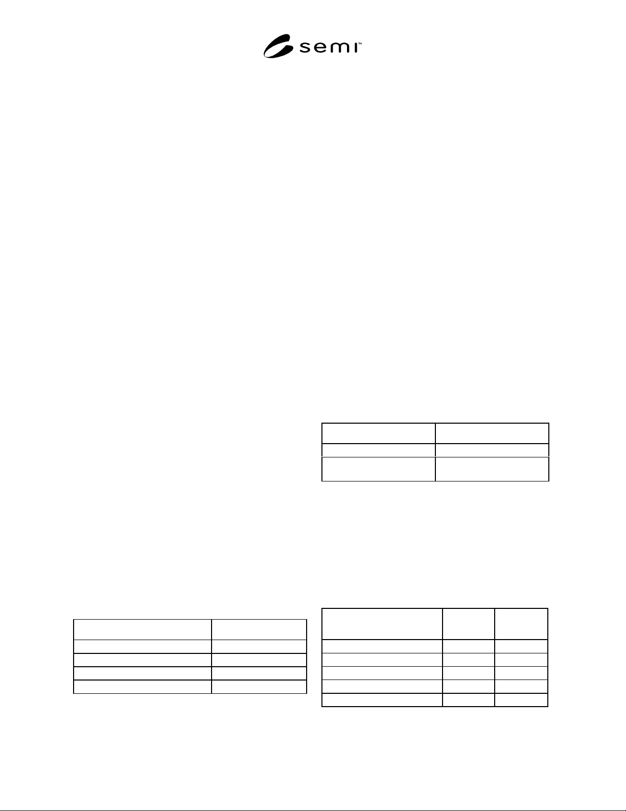
8.2.5 Flatness — See table below:
Table 1 Flatness
Flatness: Seal Area: Seal Ring Size Flatness (TIR)
0–6.35 mm (0"–0.250") 0.051 mm max. (0.002")
6.37–12.7 mm (0.251"–0.500") 0.076 mm max. (0.003")
12.72 –25.4 mm (0.501"–1.000") 0.101 mm max. (0.004")
25.42 mm and up (1.001") 0.004 in/in
8.3 Ceramic Metallized Surfaces
8.3.1 Voids
8.3.1.1 Seal Area — maximum of 3 voids permitted.
No more than two voids per side of 0.010" diameter
maximum each. Any two voids must be separated by
0.030" (0.762 mm) minimum, not to degrade the seal
width by more than 25%.
8.3.1.2 Footprint — Two voids per pad 0.254 mm
(0.010") diameter maximum. A contiguous path must
never be reduced by more than 1/3 the minimum design
width.
8.3.1.3 Wire Bond Fingers — A void-free area 0.254
mm (0.010") × 0.254 mm (0.010") or as defined by the
customer drawing.
8.3.1.4 Heat Exchange Attach Area — (if designated)
The major dimension of a void shall not exceed 0.508
mm (0.020") and all voids must be separated by 0.762
mm (0.030"). Total void area to be equal or less than
10%.
8.3.1.5 Die Attach Surface — Three voids of 0.010"
diameter are the maximum allowed separated by 0.030"
minimum.
NOTE: Voids within 0.015" of a cavity wall 0.381 mm are
excluded from this requirement.
Table 2 Die Attach Area Flatness Limits
Die Attach Pad Dimension TIR Flatness
0-12.7 mm (0–0.500") 0.51 mm (0.002" max.)
12.72–19.5 mm (0.501"–
0.750")
0.088 mm (0.0035" max.)
8.3.1.6 Internal Metallization — Voids shall not break
continuity between wire bond fingers and the
corresponding contact pad. The user may specify
additional resistance and capacitance parameters for
each application.
8.3.2 Burrs and Projections — Shall not exceed the
specification of Table 3.
Table 3 Maximum Height of Burrs and Projections
Maximum
Inches Height mm
Wire Bond Finger Area 0.001 (0.025)
Seal Area 0.001 (0.025)
Die Attach Surface 0.001 (0.025)
Contact Pad 0.002 (0.051)
Heat Exchanger Attach Area 0.003 (0.076)