semi合集-English.pdf - 第285页
SEMI E47-0301 © SEMI 1995 , 2001 4 Figure 2 Orientation Po ssibilities NOTICE: SEMI makes no warranties or representa-tion s as to the suitability of the specificatio n set forth herein for any particular application. T …
SEMI E47-0301 © SEMI 1995, 20013
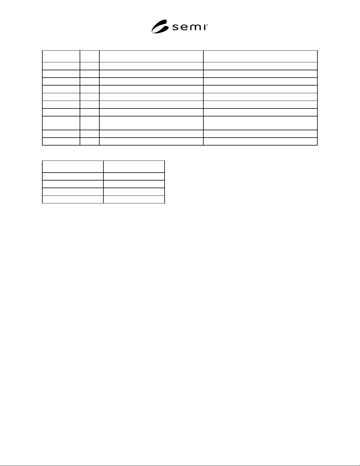
Table 1
Handling Dimensions for 150 mm (6 in.) Pod Handling Dimensions for 200 mm (8 in.) Pod
Handle: A1 215.0 mm ± 0.5 mm (8.464" ± 0.019") 305.0 mm ± 0.5 mm (12.008" ± 0.019")
A2 107.50 mm ± 0.25 mm (4.232" ± 0.01") 152.50 mm ± 0.25 mm (6.004" ± 0.01")
A3 6.0 mm ± 0.2 mm (0.236" ± 0.008") 5.65 mm ± 0.2 mm (0.222" ± 0.008")
A4 90° ± 0.2° 90° ± 0.2° (90° ± 0.2°)
A5 14 mm min. (0.551" min.) 20 mm min. (0.787" min.)
A6 30 mm ± 0.2 mm (1.181" ± 0.008") 30.0 mm ± 0.2 mm (1.181" ± 0.008")
A7 50 mm ± 0.2 mm (1.969" ± 0.008") 50.0 mm ± 0.2 mm (1.969" ± 0.008")
A8 148 mm min., 215 mm max. (A1)
(5.827" min., 8.464" max.)
148 mm min., 305 mm max. (A1)
(5.827" min., 12.008" max.)
Handle Height: B1 158 mm ± 1.0 mm (6.220" ± 0.039") 150.4 mm ± 1.0 mm (5.921" ± 0.039")
Handling Area: B2 30 mm min. (1.181" min.) 30 mm min. (1.181" min.)
Table 2
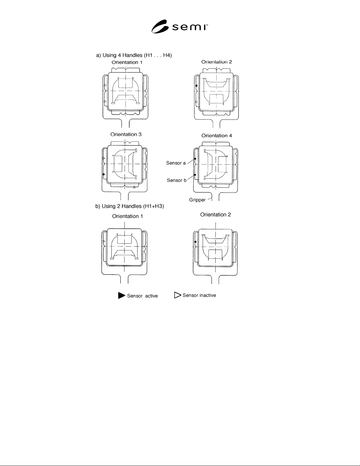
Orientation # Orientation Notch
1void
2 ON a
3 ON b
4 ON a+b
SEMI E47-0301 © SEMI 1995, 2001 4
Figure 2
Orientation Possibilities
NOTICE: SEMI makes no warranties or representa-tions as to the suitability of the specification set forth herein for
any particular application. The determination of the suitability of the specification is solely the responsibility of the
user. Users are cautioned to refer to manufacturer’s instructions, product labels, product data sheets, and other
relevant literature respecting any materials mentioned herein. These specifications are subject to change without
notice.
The user’s attention is called to the possibility that compliance with this specification may require use of
copyrighted material or of an invention covered by patent rights. By publication of this specification, SEMI takes
no position respecting the validity of any patent rights or copyrights asserted in connection with any item mentioned
in this specification. Users of this specification are expressly advised that determination of any such patent rights or
copyrights, and the risk of infringement of such rights, are entirely their own responsibility.
Copyright by SEMI® (Semiconductor Equipment and Materials
International), 3081 Zanker Road, San Jose, CA 95134. Reproduction o
f
the contents in whole or in part is forbidden without express written
consent of SEMI.
SEMI E47.1-0305 © SEMI 1997, 2005 1
SEMI E47.1-0305
PROVISIONAL MECHANICAL SPECIFICATION FOR FOUPS USED TO
TRANSPORT AND STORE 300 mm WAFERS
This specification was technically approved by the Global Physical Interfaces & Carriers Committee and is
the direct responsibility of the North American Physical Interfaces & Carriers Committee. Current edition
approved by the North American Regional Standards Committee on December 10, 2004. Initially available
at www.semi.org February 2005; to be published March 2005. Originally published in 1997; previously
published November 2004.
1 Purpose
1.1 This standard partially specifies the FOUPs used to transport and store 300 mm wafers in an IC manufacturing
facility.
2 Scope
2.1 This standard is intended to set an appropriate level of specification that places minimal limits on innovation
while ensuring modularity and interchange-ability at all mechanical interfaces. Most of the requirements given in
this specification are in the form of maximum or minimum dimensions with very few required surfaces. Only the
physical interfaces (other than the door mechanism and kinematic couplings) for FOUPs are specified; no materials
requirements or micro-contamination limits are given. The enclosure specified in this standard can be a sealed
minienvironment, but it could also just be a box with well-defined interfaces.
2.2 The FOUP has the following components and sub-components:
Key:
Required feature
Optional feature
top
top handling flange
center hole on top handling flange
3 kinematic grooves on top handling flange (optional)
interior
cassette (with supports for 13 or 25 wafers)
wafer capture mechanism
2 end effector exclusion zones
sides
2 side fork-lift flanges (optional)
ergonomic manual handles (optional)
door
holes for latch keys that lock the door to the FIMS interface when the door is unlatched from the FOUP
holes for registration pins
door sensing pads
bottom
4 bottom conveyor rails (with the bottom of the front seal zone acting as the fourth rail and the rear rail
optional)