semi合集-English.pdf - 第1941页
SEMI E54.2-0698 © SEMI 1998, 2004 5 5.x.3 Na me1 Object Behavior — Describe the object states and sub-states as needed with a Ha rel State Diagram(s): Figure Harel State Di agram Provide a state definition tab le as give…

SEMI E54.2-0698 © SEMI 1998, 2004 4
NOTE 2: The device may actually consist of multiple devices (e.g., Mass Flow Device includes a Controller device and a Meter
device), in which case multiple sections should be created - one per device.
5.1.x General Requirements
5.1.x.1 Device Objects — All objects are defined in terms of their object name and instance identifier. Identifiers
for all objects described in this document are summarized in Table m.
Table m NamedDevice Device Objects
Referenced Document Section Object Name Object Identifier Minimum Instances Maximum Instances
All parameters used by the device' s services can be summarized using the table (Table n). This is optional, as the
parameters are further defined in association with specific objects (see 5.x.2).
Table n Parameter Definition Table
Parameter Name Data Type Tag Description
For each Object in Table m, a section (5.x) is created as below, beginning with 5.2.
5.x Name1 Object
5.x.1 Name1 Object Attributes — Provide the object attribute information using the table (Table o) below.
Table o Object Name1 Attributes
Attribute Name Definition* Attribute Identifier Network Access Form Storage Class Required
* The definition column can be omitted if the definitions immediately follow the table. The definitions can be provided as subsections.
Where appropriate, provide initial and default values for object attributes. This can be done as a table.
5.x.2 Name1 Object Services — Describe the services provided by this object using the following table (Table p) to
list the services:
Table p Object Name1 Services
Service Service Identifier Type Description
Provide a detailed description of each service, including a definition of the parameters for the service. The
parameters can be defined using the following table (Table q) format:
Table q Service1 Service Parameter Definitions
Parameter Request/Indication Response/Confirmation Data Type* Description
* This column can be removed if there is an overall parameter definition table (Table n) included in the specification.
SEMI E54.2-0698 © SEMI 1998, 2004 5
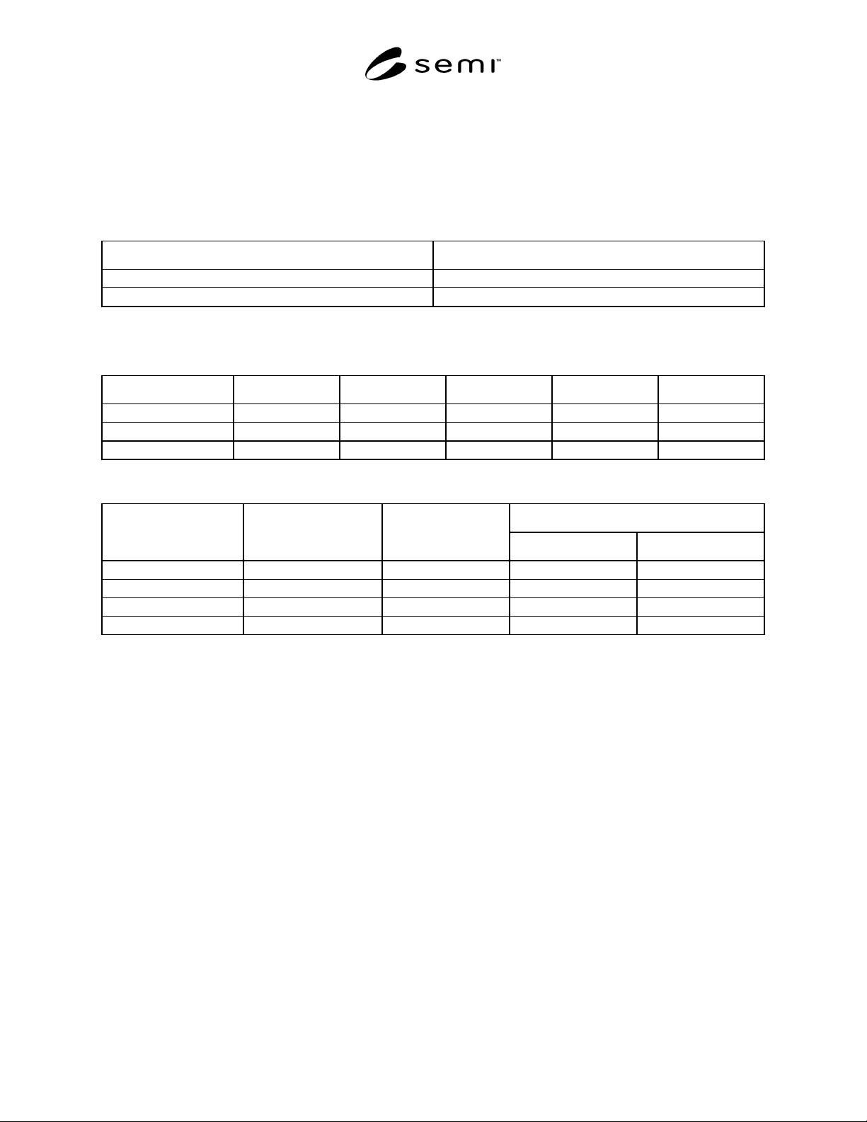
5.x.3 Name1 Object Behavior — Describe the object states and sub-states as needed with a Harel State Diagram(s):
Figure
Harel State Diagram
Provide a state definition table as given in Table r. More than one state table could be added if a device is
sufficiently complex. Put in any text needed to explain object states.
Table r Name1 Object Behavior State Descriptions
State Name Description
Describe the state transitions using a table as given in Tables s or t. More than one table could be needed.
Table s Name1 Object Behavior State Transition Table
Event or Transition # Current State Trigger New State Action(s) Comments
Table t Name1 Object Behavior State Transition Matrix
State 3
Event Number State 1 State 2
Sub A Sub B
1
2
3
4
9 Template for Part 1 of an SANCS Ancillary Standard
9.1 The body of the ballot should then contain the following sections:
1 Purpose
This section contains wording describing the purpose with customization for the specific protocol. A “Background
and Motivation” subsection could be included to generally describe the protocol.
2 Scope
This section contains wording describing the scope with customization for the specific protocol.
3 Limitations
This section contains wording describing the limitations customized for the specific protocol. Any limitations of
CDM or SDMs support, due to the protocol, should be identified.
4 Referenced Documents
This section contains wording describing the referenced documents with additional references to protocol
specification documentation and any support documentation as required for complete specification of the protocol
(two subsections). A clearly defined mechanism is specified for obtaining any documentation that is not publicly
available or available from SEMI.

SEMI E54.2-0698 © SEMI 1998, 2004 6
5 Terminology
The various protocols and the CDM invariably use
different terminology. A mapping is made between the
CDM terminology and the terminology used in
discussing the protocol. For example, a CDM Service
implementation may be defined as an Action in the
NCS. This terminology mapping is explicitly covered
completely in the “Terminology” section. A mapping
table is desirable that contains a column listing of the
CDM terms in the same order as defined in the CDM
document, mapped to terminology used in the NCS
document. This NCS terminology and any additional
terminology is defined in a subsection (e.g., Section
5.2).
6 Communication Protocol High Level Structure
A basic description of the protocol is provided in
Section 6. The main purpose of Section 6 is to give the
reader a general understanding of what will be
specifically presented in the remainder of the
subsections in Section 6.
The rest of the subsections in Section 6 should be
devoted to describing the communications standard in
terms of the OSI seven-layer model (one subsection for
each layer) and any network management services.
Each of the OSI seven layers should be addressed and
specified either directly or through reference; for each:
• If an OSI layer is not supported/defined, this is
stated explicitly.
• Choices among protocol options are made,
specified, and explained where appropriate. A
complete summary of protocol choices specified
and protocol options allowed should be
summarized in a subsection of this section of the
specification.
The Physical
layer is specified either directly or through
reference (signaling, bus arbitration, baud rate,
transceivers, cabling, connectors, etc.).
The Data link layer is specified either directly or
through reference (packet/frame specification and node
addressing).
The Network
layer is optional.
The Transport
layer elements are specified either
directly or through reference; message segmentation
and reassembling should be supported as no message
length limits are indicated in CDM or SDM' s. This
support should be provided as a transport layer service.
Note that this functionality may alternatively be
provided at the application layer by protocols unable to
support it at the transport layer; if this is the case, it is
explicitly stated in the description of transport layer
support. Connection support would be specified here as
appropriate.
The Session
layer is optional.
The Presentation
layer is optional.
The Application
layer is specified. The document
defines (explicitly or through reference) how objects
are structured, identified, and addressed. Thus, it should
also define how object attributes are addressed and how
object request and notify services are addressed and
communicated. This section also defines the application
object to object communication mechanism which
should include or reference a communication state
model. This communication model should clearly
indicate whether or not the protocol is connection
oriented.
Network Management Services
may be defined in a
separate subsection.
7 Required Object Types
This section identifies specific objects that must be
supported to enable the CDM. The document should
identify how the CDM structure (Objects and relations)
fits into the protocol application layer foundation. Any
identifiable protocol object hierarchy should be
introduced here. Specifically, the following are defined:
• The implementation of all CDM objects (DM,
SAC, AE, and all subclasses) defined to the extent
that these objects are defined in CDM
documentation.
• Specific addressing/referencing for CDM objects
(attributes, services, etc.) defined as necessary so
as to specify access to CDM objects as required by
the CDM standard specification. Attributes and
services are further specified as necessary so that
the protocol required to access specific attributes
and services is fully defined. For example, a CDM
service may be defined as a “new” SANCS service
or mapped to an existing SANCS service (if an
appropriate candidate has already been defined in
the protocol specification).
• Any limitations among CDM object options are
identified.
• Any additional capabilities required of, or optional
for, CDM objects (e.g., attributes, services, and/or
behavior) are identified.
• Any additional required objects (e.g., network
management object) identified and their interaction
with the CDM objects (e.g., connection
management object) should be specified.