semi合集-English.pdf - 第4610页
SEMI D41-0305 © SEMI 2005 1 SEMI D41-0305 MEASUREMENT METHOD OF SEMI MURA IN FPD IMAGE QUALIT Y INSPECTION This standard was technically approved by the Global Flat Panel Display - Factor y Committee and is the direct re…
SEMI D40-0704 © SEMI 2004 3
Substrate
Support Member
Beveled region
Support Position
Shorter Support Span
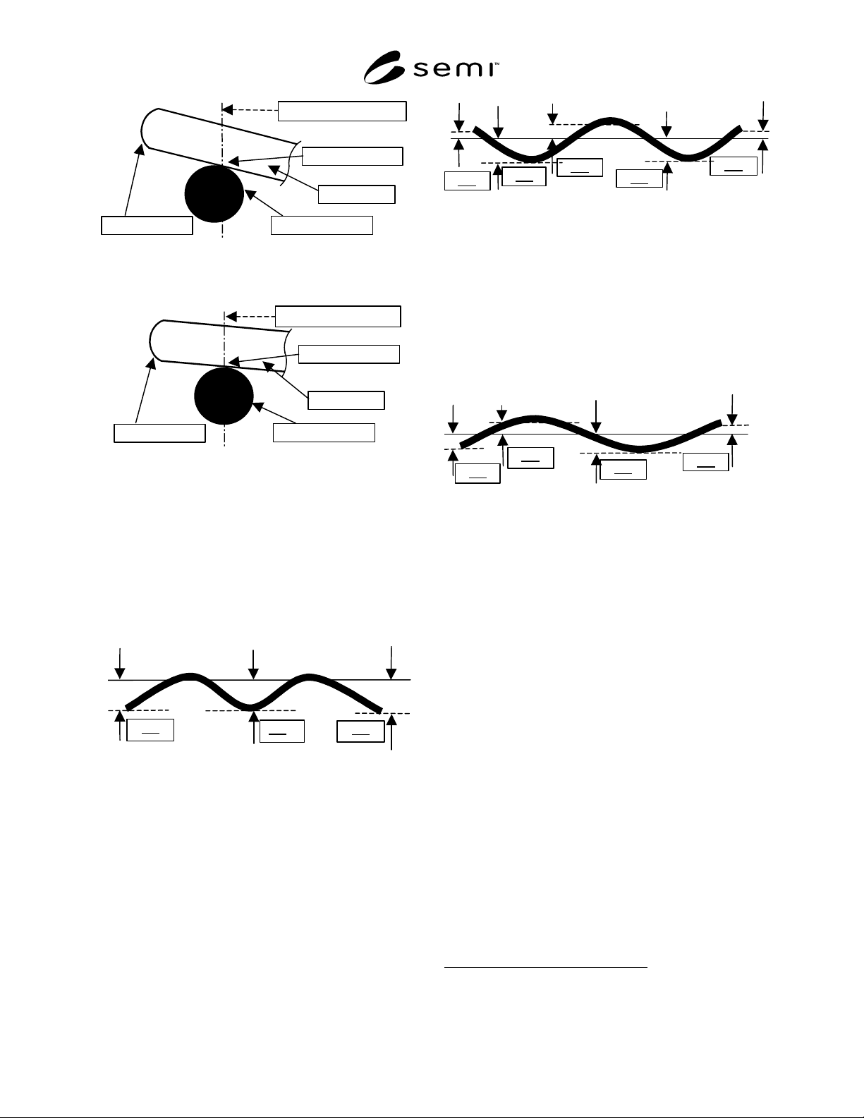
Figure 9
Position on Small Sag
Substrate
Support Member
Beveled region
Support Position
Longer Support Span
Figure 10
Position on Large sag
5.1.2.3 M Type the type has an alphabetic “M”
shape, which mixes the convex shape and the concave
shape, as shown in Figure 11. This substrate shape is
named “M type”. M type consists of all sag and
requires sag to exist at both edge regions of the
substrate, even if the substrate has a continuous wave or
corrugation in its shape.
Sag
Sag
Sag
Figure 11
M Type Substrate Shape
5.1.2.4 W Type the type has an alphabetic “W”
shape, which mixes the convex shape and the concave
shape, as shown in Figure 12. This substrate shape is
named “W” type. W type combines sag and lift. Also W
type requires lift to exist at both edge regions of the
substrate, even if the substrate has a continuous wave or
corrugation in its shape.
Lift
Lift
Lift
Sag
Sag
Figure 12
W Type Substrate Shape
5.1.2.5 S Type the type has a rotated alphabetic “S”
shape, which mixes the convex shape and the concave
shape, as shown in Figure 13. This substrate is named
“S” type. S type combines sag and lift. Also S type
requires an asymmetrical shape, which consists of sag
and lift at both edge regions, even if the substrate has a
continuous wave or corrugation in its shape.
Sag
Lift
Sag
Lift
Figure 13
S Type Substrate Shape
6 Related Documents
6.1 SEAJ
1
(Semiconductor Equipment Association of
Japan) Liquid Crystal Display Manufacturing
Equipment Dictionary
NOTICE: SEMI makes no warranties or
representations as to the suitability of the standards set
forth herein for any particular application. The
determination of the suitability of the standard is solely
the responsibility of the user. Users are cautioned to
refer to manufacturer' s instructions, product labels,
product data sheets, and other relevant literature,
respecting any materials or equipment mentioned
herein. These standards are subject to change without
notice.
By publication of this standard, Semiconductor
Equipment and Materials International (SEMI) takes no
position respecting the validity of any patent rights or
copyrights asserted in connection with any items
mentioned in this standard. Users of this standard are
expressly advised that determination of any such patent
rights or copyrights, and the risk of infringement of
such rights are entirely their own responsibility.
1 Semiconductor Equipment Association of Japan, 4F Grand Maison
Shinjuku Gyoen., 1-7-10 Shinjuku Shinjuku-ku, Tokyo 160-0022
Japan Phone 03.3353.7651 Fax 03.3353.7970
Copyright by SEMI® (Semiconductor Equipment and Materials
International), 3081 Zanker Road, San Jose, CA 95134. Reproduction o
f
the contents in whole or in part is forbidden without express written
consent of SEMI.

SEMI D41-0305 © SEMI 2005 1
SEMI D41-0305
MEASUREMENT METHOD OF SEMI MURA IN FPD IMAGE QUALITY
INSPECTION
This standard was technically approved by the Global Flat Panel Display - Factory Committee and is the
direct responsibility of Japanese Flat Panel Display Factory Automation Committee. Current edition
approved by the Japan Regional Standards Committee on November 24, 2004. Initially available at
www.semi.org January 2005; to be published March 2005.
1 Purpose
1.1 This standard will define the application of the formula derived in SEMI D31 to various test conditions closed
to visual inspection for MURA in FPD image quality inspection.
1.2 SEMI D31 has derived a formula to detect defects and blemishes in FPD in comparison with human eyes and
CCD based instruments.
1.3 In general the difficulty of implementing instruments to replace human inspector lays on human factor variation
with its origin and location.
2 Scope
2.1 This standard is applicable to FPDs. This standard mainly deals with both the measurement method of Semu
and the revised definition of Semu. The target display size is typically from 8”(20.3cm) to 30”(76.2cm) diagonal.
NOTICE: This standard does not purport to address safety issues, if any, associated with its use. It is the
responsibility of the users of this standard to establish appropriate safety and health practices and determine the
applicability of regulatory or other limitations prior to use.
3 Limitations
3.1 In this standard, the target of measurement, Mura, is limited as below.
3.2 Line defects narrower than a pixel and pixel dot defects are not the subject of this standard. In this issue, this
standard follows SEMI D31.
3.3 In this standard, it is dealt with monochrome displays like gray scale patterns in color patterns. In this issue, this
standard follows SEMI D31.
4 Reference Standards
4.1 SEMI Standards
SEMI D31 —Definition of Measurement Index (Semu) for Luminance Mura in FPD Image Quality Inspection
4.2 Other Documents
Flat Panel Display Measurement Standard, VESA FPDM 2.0, June 2001, IEC 61747-6.
NOTICE: Unless otherwise indicated, all documents cited shall be the latest published versions.
5 Terminology
5.1 This standard follows SEMI D31 in terminology.
5.2 Abbreviations and Acronyms
5.2.1 JND — abbreviation for Just Noticeable Difference used in the field of Psychophysics; for a certain stimulus,
the smallest change in stimulus (luminance, for example) where a difference can be perceived. Specifically, it is
often used to indicate a statistical value where the probability of the difference being “perceptible” is 50% and the
probability of the difference “not being perceptible” is 50%. Also expressed using lower case letters, jnd.

SEMI D41-0305 © SEMI 2005 2
5.3 Definitions
5.3.1 Dynamic Range — the divided ability from a minimum detecting level to a maximum detection level of a
CCD equipment.
5.3.2 Gray Scale — gray scale on an image display. This standard indicates level 32 out of 64 level gray scale.
5.3.3 L0 Display — gradation 0 out of 64. (Pitch Black)
5.3.4 L63 Display — gradation 63 out of 64 (Completely white)
5.3.5 Luminance Accuracy — the error ratio of the luminance.
5.3.6 Measuring points — the number of CCD sensors.
5.3.7 Semu — Semi Mura, Measurement index for Mura, defined in this standard. Please refer toSEMI D31.
5.3.8 Viewing direction — the angle between the CCD equipment and the test sample.
6 Related Definitions for Mura Measurement
6.1 Mura is a Japanese term meaning blemish and has been adopted in English to provide a name for imperfections
of the display pixel matrix surfaces that are visible when the display is in operation. Inspect the display surface
while displaying a white full screen, a black full screen, and a dark gray full screen (VESA FPDM 2.0). In many
case, the Mura phenomena is detected by human eyes. But this is very confusing in the quality aspect. And it is very
difficult to quantify the level.
6.2 The definition in SEMI D31 shows mainly that Luminance Mura is related with the size of Mura. Therefore this
standard will follow the Cjnd concept.
6.3 Semu Definition
6.3.1 Under specific conditions, the below regression function can explain the level of Mura between the area and
contrast for Human Mura JND. (Refer to SEMI D31.)
Cjnd = F (Sjnd) = 1.97/Sjnd
0.33
+ 0.72
Cjnd: Contrast of Mura at JND
(Unit: % relative to background = 100%)
Sjnd: The area of Mura at above contrast (Units: mm
2
)
6.3.2 In the above equation, contrast at JND is inversely proportional to the area raised to the 0.33 powers. In short,
it indicates that as Mura the area gets smaller, only darker Mura can be sensed.
6.3.2.1 For the subject Mura, the Mura level, Semu, can be calculated using the below formula.
Semu = |Cx| / Cjnd
= |Cx| / F (Sx)
= |Cx| /(1.97/Sx
0.33
+ 0.72)
Cx: Average contrast of Mura being measured (Unit: % relative to background = 100%)
Sx: The surface area of Mura being measured (mm
2
)
7 Measurement Method
7.1 Environment Conditions:
Temperature: 25 ± 2°C
Humidity: 65 ± 20% RH
Illumination of surrounding: in a dark room below 10 lux
Air flow: no wind