semi合集-English.pdf - 第4253页
SEMI F78-0304 © SEMI 2003, 2004 6 Sample test welds shall be made when any of the following conditions exist: 11.5.1 Start of shift (in) or e nd of shift (out). 11.5.2 Change of weld param eters. 11.5.3 Change of m a ter…
SEMI F78-0304 © SEMI 2003, 2004 5
may contaminate the tubing being faced. The cutting or
facing shall not be of a abrasive type.
8.7 Severing or parting equipment shall be of the
machining type that will separate the tubing without
contaminating the ID of the tubing. Wheel type cutters
designed to cut stainless steel and CRAs are allowed
with purge. Dry saws of orbital type or cutoff are
allowed only when followed by cleaning to 12.5. All
cut ends shall meet the tolerances for facing equipment
or be followed by end preparation with a facing tool.
9 Materials
9.1 All materials to be welded shall be manufactured to
ASTM specifications and so certified by the
manufacturer. Certification shall conform to ASTM
A450, Section 25.
9.2 All seamless austenitic stainless steel tubing shall
be in conformance with SEMI F20 or customer
specification.
9.3 A backing (ID) gas is required during welding, and
while tacking (if tacking is used).
9.4 Weld parameters are affected by the choice of
shield gas. Argon, due to its effectiveness and material
compatibility, is the most commonly selected shielding
and purging gas. Argon and helium are inert and
therefore have no effect on the weld metal. These gases
do have very different ionization potentials, thermal
conductivity, and reactivity.
9.5 Argon/hydrogen mix is a reducing gas that avoids
the formation of oxides. It also reduces the amperage
required for a given ID weld bead width while reducing
the OD bead width. Argon/hydrogen mixes adversely
affect high ferrite materials (above 80% ferrite). Use of
argon/hydrogen mixes will shorten tungsten electrode
life. The weld parameters will be affected by hydrogen
to argon percentages. Hydrogen mixes above 5 vol%
are not recommended for safety reasons.
9.6 Nitrogen will cause instability of the arc in mixes
above 3 vol% in the shield (OD) purge gas. It is a
acceptable backing (ID) gas for austenitic stainless and
many CRAs. Nitrogen when exposed to welding
temperatures will cause nitride formation in some high
ferrite materials (above 80% ferrite). Use of nitrogen
mixes in the shielding (OD) gas will shorten the
tungsten electrode life.
9.7 The ID purge gas will be certified to 99.9997%, or
less than 3 ppm total contaminants (moisture, oxygen,
and other contaminants).
10 Safety Precautions
10.1 This practice does not purport to address all of the
safety issues associated with its use. It is the
responsibility of the users of this standard to establish
appropriate safety and health practices and determine
the applicability of regulatory limitations prior to use.
10.2 Welding equipment used to make welds shall be
operated in accordance with the manufacturer’s
operating and safety instructions.
10.3 All welding performed under this practice shall
conform to the applicable requirements of ANSI/ASC
Z49.1.
10.4 Welding gas mixtures containing more than
5 vol% H
2
are not recommended due to the potential for
fire hazard.
10.5 Do not reweld stainless steel that has been used
for corrosive gas delivery.
10.6 See Appendix 1 for information on stainless steel
and welding fume.
11 Test Specimens: Couponing
11.1 Prior to the welding of a particular size, wall
thickness, and alloy, a primary standard sample weld
shall be made, sectioned, and analyzed at the job site.
The primary standard sample weld shall become the on-
site work sample against which other welds of the same
size, wall thickness, and alloy are judged. This on-site
work sample may be used indefinitely or reproduced
each day at the discretion of the examiner.
11.2 The primary standard sample weld shall be
checked for compliance with SEMI F81, “Specification
for Visual Inspection and Acceptance of Gas Tungsten
Arc (GTA) Welds in Fluid Distribution Systems in
Semiconductor Manufacturing Applications.” Coupons
shall be cross-sectioned and inspected visually. Weld
coupon criteria are the same criteria for all system
welds.
11.3 Once a sample weld is found to be acceptable, all
essential and supplementary essential variables shall be
documented in the procedure qualification record.
11.4 Any significant deviation(s) from the on-site
work sample will cause the weld(s) to be rejected.
Rejected welds shall be removed and replaced.
11.5 Sample test welds shall be made periodically.
These sample test welds shall be compared to the on-
site work sample and checked for compliance with
SEMI F81. Deviation from the on-site work sample or
SEMI F81 shall be cause for rejection. If the weld
inside diameter is inspectable using a sight tube or other
device, sample test welds may be production welds.

SEMI F78-0304 © SEMI 2003, 2004 6
Sample test welds shall be made when any of the
following conditions exist:
11.5.1 Start of shift (in) or end of shift (out).
11.5.2 Change of weld parameters.
11.5.3 Change of material (heat number).
11.5.4 Change of tube size or wall thickness.
11.5.5 Change of ambient temperature ± 20°F
(± 11°C).
11.5.6 Change of source of power to power supply to
include addition or subtraction of extension cords.
11.5.7 Change or removal of the weld electrode.
11.5.8 Any change of equipment such as weld head,
weld head extensions, or power supply.
11.5.9 Any time that a weld discrepancy is noted by
the welding operator.
11.5.10 Any significant change of ID or OD purge gas
(source or flow rate).
11.6 All couponing shall use the same ID purge gas
and OD shielding gas as the production weld (Figure 2).
12 Procedure
12.1 Documented procedures shall exist for each weld
configuration including all parameters (including purge
times, orifice sizes, purge rates, and internal pressure).
12.2 Check parameters and verify that they are in
accordance with the qualified welding procedure.
12.3 Perform only one weld joint at a time.
12.4 Joint Preparation Procedure
12.4.1 All cutting of component or tubing weld ends
shall be done with a sharp-edged tool. No lubricants of
any kind shall be allowed.
12.4.2 All component and tubing weld ends shall be
de-burred after cutting.
12.4.3 Surfaces for welding shall be clean and shall be
free from oxidation, discoloration, oil, scale, chips, or
other material that is detrimental to welding.
12.4.4 Unless tubing is to be cleaned afterward, tubing
shall be opened, cut, faced, and deburred in a required
cleanroom environment, leaving no visible particulates
inside the cut end.
12.4.5 The tube shall be faced to remove all
necking/wedging caused by the tube cutters (Figure 3).
For tube cutting, use a wheel cutter with lathe-type
facing tool or a special designed power saw with
alignment guide. Do not use lubricant. If any “nicks”
are found, reface or discard the tube.
12.4.6 Unless tubing is to be cleaned afterward, all
weld end preparation shall be done in such a manner as
to minimize the introduction of contaminants into the
system. When bending, cutting, or facing tubing a
positive purge must be used to remove any particles.
12.4.7 The prepared end shall conform to ASTM A
632 (or ASTM A 269 ≥ ½ in. OD) tubing specification
with regard to ovality and wall thickness.
12.4.8 The weld fit-up gap shall not exceed 0.003 in.
(0.08 mm) when the entire circumference is affected
(Figure 4). The maximum gap in any one area shall not
exceed 0.006 in. (0.15 mm) (Figure 5). The prepared
end shall be square to tube run within ¼° (angle).
12.4.9 After preparing, debur the inside diameter
carefully and lightly. Do not scratch the inside
diameter. Any scratched tubes shall be reprepped or
scrapped.
12.4.10 Chamfering is undesirable. The maximum OD
or ID chamfering shall be less than 10% of the wall
thickness or 0.005 in. (0.13 mm) whichever is less
(Figure 6).
12.4.11 All components shall be maintained in a clean
condition until welded into the system.
12.4.12 All benders, cutters, facing tool collets, or
brushes that are to be used on stainless tubing or alloy
tubing shall not be used on carbon steel tubing and care
shall be used on mixing alloys. All tools shall be
maintained in clean condition and shall be free of
grease, oil, dirt, and other foreign matter. Avoid cross-
contamination from dissimilar materials.
12.4.13 Bends on the tubing shall not be made in the
weld area.
12.4.14 Use only tools and handling techniques that
will not mar, disturb the shape of, or in any way reduce
the conformance to specifications of the materials used
in this system.
12.4.15 Tube ends shall be covered while the purge is
removed using a technique that will minimize the
amount of infiltration or contamination. Covers shall be
of non-particulating material.
12.4.16 Remove protective cover immediately prior to
performing the weld.
12.5 Tube Cleaning
12.5.1 It is recommended that all cut tubing be cleaned.
At a minimum, tubing contaminated during preparation
shall be cleaned using a high purity cleaning procedure.
SEMI F78-0304 © SEMI 2003, 2004 7
12.5.2 In the case of contaminated tubing, or if a cut-
out or saw cut is necessary, the following cleaning
procedure shall be used:
12.5.2.1 Primary rinse in cold running DI water.
12.5.2.2 Secondary rinse in hot [80°C (176°F)] DI
water.
12.5.2.3 Final rinse in DI water with pressure flush.
12.5.2.4 Blow dry with pressurized hot [150°C
(318°F)] N
2
. Ensure that drying occurs immediately
after final rinse.
12.5.2.5 Use immediately or cap and seal in plastic
sleeves.
12.6 Purging
12.6.1 All welds must use a positive and repeatable
form of ID purge pressure control. See Table 1 for
suggested settings and refer to Figures 7 and 8.
12.6.2 Production welds must use the same flow rates
and ID purge pressures as the qualified coupon weld.
12.6.3 During welding, all tubes, fittings, valves, sub-
assemblies, and all other components shall be
continuously purged.
12.6.4 Automatic orbital welding equipment shall
supply a constant gas shield to the weld head during
welding.
12.6.5 During all welding, a sufficient amount of
purge/shield gas shall be maintained until the weld has
cooled to a temperature where it can be handled, and
until the weld head is removed from the newly welded
parts.
12.6.6 Both purge/shield gas supply lines shall contain
flow indicators to ensure proper purging.
12.6.7 For welding of installed systems that will not be
subsequently cleaned, once construction begins, an ID
purge shall be maintained, either a flowing purge of 3
to 5 scfh (1 to 2 L/min.) or a block purge of 30 psi (206
kPa), until the system is complete. A flowing purge is
recommended on UHP systems.
12.6.8 The purge supply shall have a means to
manifold it so that there is a single point of connection
for each line under construction.
12.6.9 Extreme care shall be taken to ensure that all
contiguous flowpaths are fully purged.
12.6.10 All dead legs must be purged out completely
prior to welding.
12.6.11 All welds shall be performed with the purge
flow established by the weld procedure specification
sweeping the weld area during and after welding.
12.6.12 Vacuum devices may be required to overcome
back pressure in components such as regulators, filters,
purifiers, check valves, or others. Dead-end
components such as gauges may be purged using a
small-diameter tube placed inside the tubing to be
welded and back-flowing purge through the weld zone.
12.6.13 Pre-purging and post-purging shall occur for as
long as necessary to avoid unacceptable weld
discoloration.
12.6.14 Light external oxidation may be removed with
a stainless steel wire brush immediately after welding.
Purge shall be maintained during the brushing process,
and care shall be taken to perform the brushing process
in an appropriate area so as not to contaminate the work
area.
12.7 Welding Electrode
12.7.1 Welding electrodes shall be changed as
frequently as necessary to prevent weld deterioration.
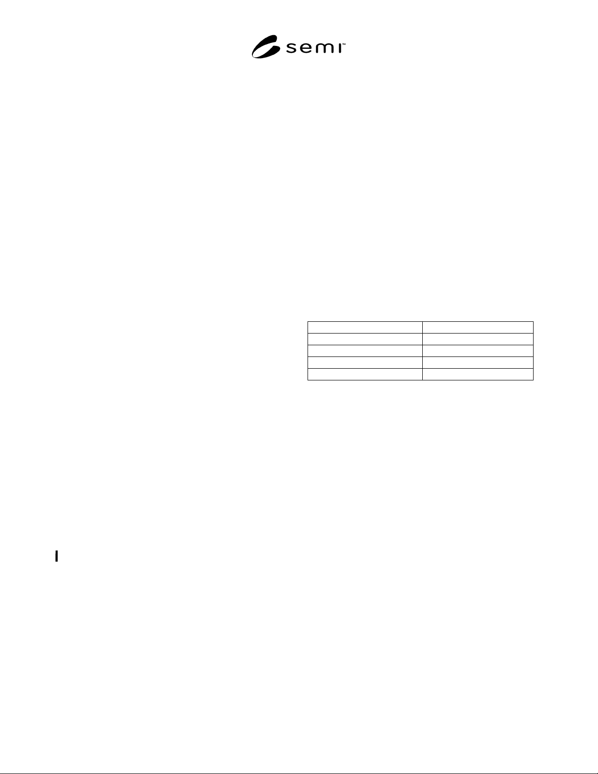
Typical number of welds per electrode is as follows:
Tube diameter Welds per electrode
¼-in. and under 25 to 50
3/8 to 1.0-in. 20 to 25
1.0 to 2.0-in. 10 to 20
2.0-in. and above 10 to 15
12.7.2 Electrode shall be cut, not broken to length.
12.8 Additional Requirements
12.8.1 Maintain sufficient distance between weld joints
and valve seats to avoid damage to valve seats or valve
stem tips when purging through the valve. Purge
through the valve to the weld when possible.
12.8.2 Valves shall be located so as to allow space to
operate the valve after installation at the job site.
12.8.3 Valves must be cool to the touch after welding
and prior to cycling to avoid damage to the seat.
12.8.4 Clean Room Welding
12.8.4.1 Welders shall follow all clean room protocol
and use non-powdered latex gloves any time that the
tubing or component to be welded is removed from
protective covering.
12.8.4.2 All tools and fixtures used for the assembly
and welding shall be maintained clean and shall not be
removed for use outside of the clean room preparation
area.
12.8.4.3 As much welding as is feasible will be
performed in the clean room preparation area in the
form of sub-assemblies.