semi合集-English.pdf - 第6889页
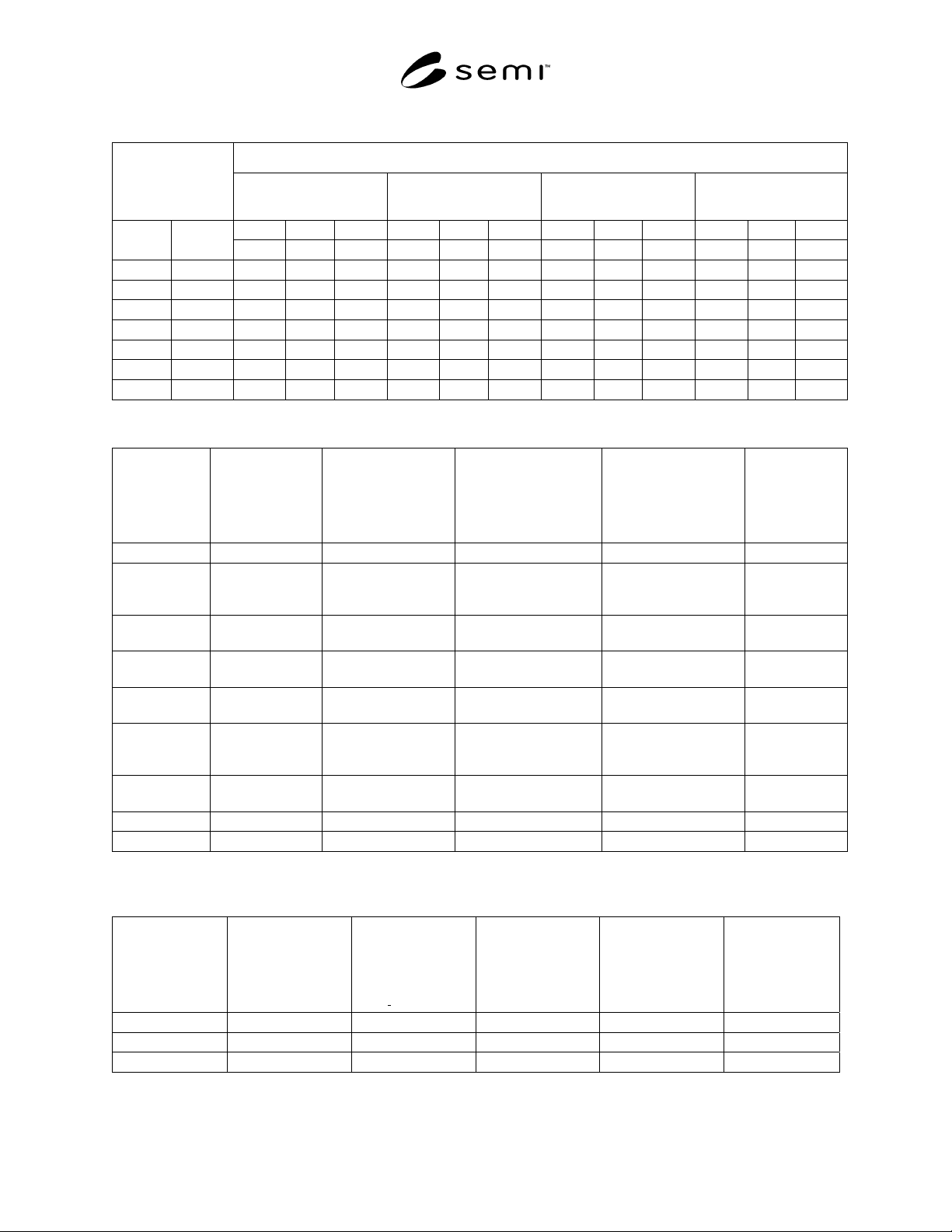
SEMI S5-0703 © SEMI 1993, 2003 4 Table 1 Critical Nitroge n Flow Rates (Q NT ) For Flow Limiting Devices Critical Flow Rate ( slm) of nitrogen at the following cylinder pr essures: Equivalent Orifice Size 700 kPa gauge (…
SEMI S5-0703 © SEMI 1993, 2003 3
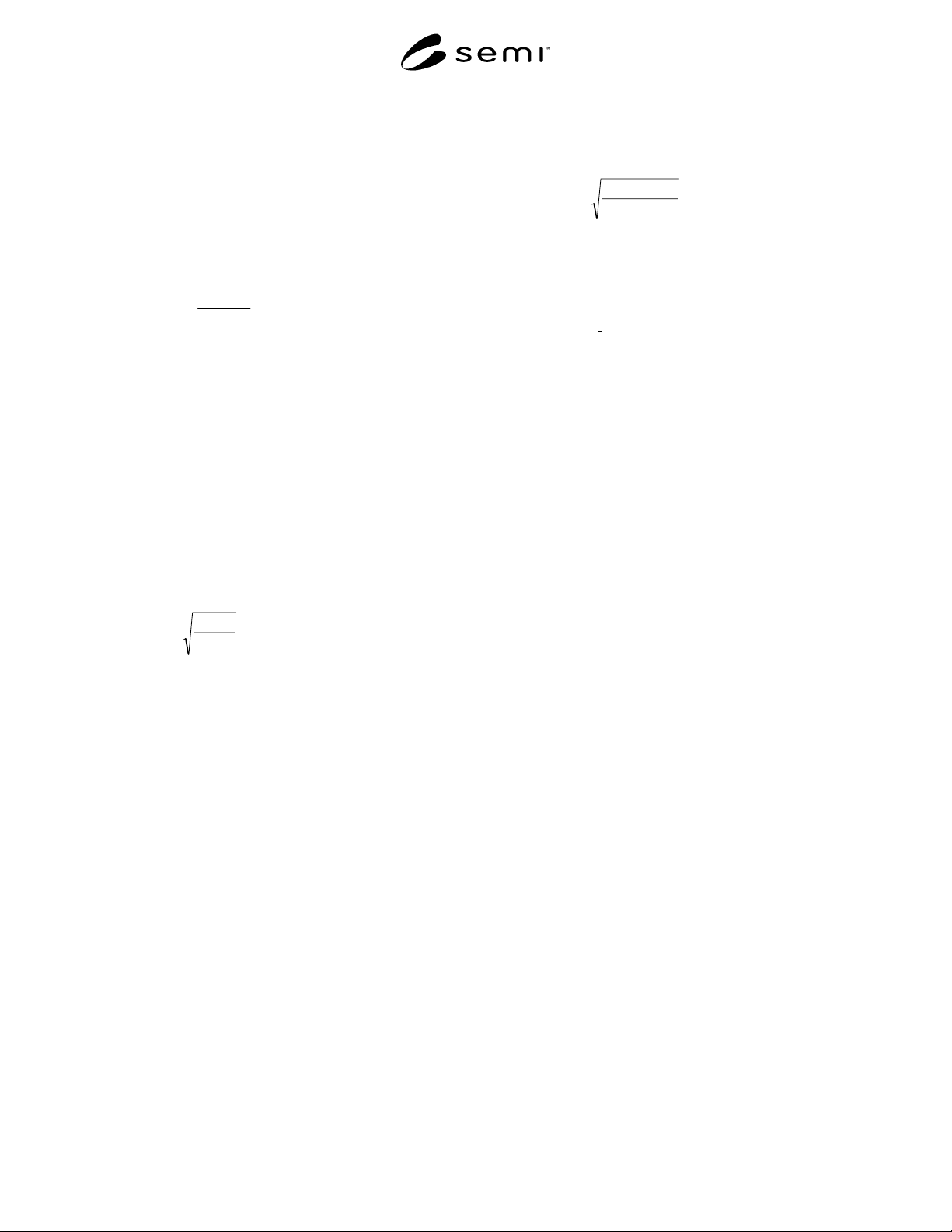
P
atm is standard atmospheric pressure 101 kPa
absolute (14.7 psia) at sea level.
P
NT
is the pressure in kPa gauge (psig) from Table 1
that produces critical flow rate Q
NT
for a given
equivalent orifice size.
EXAMPLE 1: What is the minimum flow rate of
nitrogen through a 0.25 mm (0.01 inch) equivalent
orifice at 862 kPa gauge (125 psig)?
Q
N
= 2.90 ×
101700
101862
+
+
= 3.5 slm nitrogen (Q
NT
= 2.90 is
the minimum flow rate at 700 kPa gauge, the minimum
flow rate for a 0.25 mm orifice at any pressure listed in
Table 1 will provide the same result.)
EXAMPLE 2: What is the maximum flow rate of
nitrogen through a 0.25 mm (0.01 inch) equivalent
orifice at 12,414 kPa gauge (1,800 psig)?
Q
N
= 4.35 ×
101700
10112414
+
+
= 68 slm nitrogen (Q
NT
= 4.35
is the maximum flow rate at 700 kPa gauge.)
7.3 Hazardous Gas Flow Rate— Flow rate correction
for gases listed in Table 2 other than nitrogen follows:
NOTE 3: This formula is only valid for critical flow,
typically where P
cyl
/ P
atm
> 2
Q
g
= Q
N
×
g
DZ)(
25.1
Equation 2. (Use Q
NT
in place of
Q
N
when the applicable cylinder pressure is listed in
Table 2.)
Q
g
is the critical flow rate in slm of the gas listed in
Table 2.
D
g
is the standard density of the gas in kg/m
3
at one
atmosphere and 0°C (32°F) listed in Table 2.
Z is the compressibility factor at P
cyl
for the gas listed
in Table 2. For pressures not listed, interpolation of Z
with Z assumed proportional to pressure and equal to
1.0 at zero pressure should provide adequate accuracy
in the pressure and temperature ranges found in this
document. For gas mixtures with the mixing gas 95%
by volume or greater, use of Z for the mixing gas
should provide adequate accuracy, for lower
percentages consult the gas supplier.
NOTE 4: Density is the reciprocal of specific volume.
Density or specific volume is frequently given at a
temperature of 21.1°C (70°F). To convert 21.1°C (70°F) to
0°C (32°F) standard density, multiply by 1.077.
EXAMPLE 3: What is the minimum flow for Nitrogen
Trifluoride through a 0.75 mm (0.03 inch) equivalent
orifice at 700 kPa gauge?
Q = 26.1 ×
)20.3)(97.0(
25.1
= 16.6 slm Nitrogen
Trifluoride (Z is interpolated at 700 kPa)
7.4 Density For Gas Mixtures — Density correction
for mixtures of gases listed in Table 2, or Table 2 and
Table 3 follows:
D
mix
=
∑
V
g
× D
g
Equation 3. (For gas mixtures, use
D
mix
in place of D
g
in Equation 2.)
V
g
is the volume fraction of each gas in the mixture.
EXAMPLE 4: What is the density for a mixture of 5%
arsine and 95% nitrogen?
D
mix
= (.05 × 3.45) + (.95 × 1.25) = 1.36 kg/m
3
8 Related Documents
8.1 CGA Standard
2
CGA V-9 Compressed Gas Association Standard for
Compressed Gas Cylinder Valves
2 Compressed Gas Association, Inc., 1725 Jefferson Davis Highway,
Suite 1004, Arlington, VA 22202
SEMI S5-0703 © SEMI 1993, 2003 4
Table 1 Critical Nitrogen Flow Rates (Q
NT
) For Flow Limiting Devices
Critical Flow Rate (slm) of nitrogen at the following cylinder pressures:
Equivalent Orifice
Size
700 kPa gauge
(102 psig)
2100 kPa gauge
(305 psig)
7000 kPa gauge
(1015 psig)
21000 kPa gauge
(3045 psig)
min. nom. max. min. nom. max. min. nom. max. min. nom. max.
mm inch
−20% +20% −20% +20% −20% +20% −20% +20%
0.15 0.006
1.04
1.31
1.57 2.86
3.57
4.29 9.21
11.5
13.8 27.4
34.2
41.0
0.25 0.01
2.90
3.62
4.35 7.94
9.93
11.9 25.6
31.0
38.4 76.0
95.0
114
0.50 0.02
11.6
14.5
17.4 31.8
39.7
47.7 102
128
153 304
380
456
0.75 0.03
26.1
32.6
39.1 71.5
89.4
107 230
288
345 684
855
1026
1.00 0.04
46.4
58.0
69.6 127
159
191 409
512
614 1216
1520
1824
1.25 0.05
72.5
90.6
108 199
248
298 640
799
959 1900
2375
2850
1.50 0.06
104
130
157 286
357
429 921
1151
1381 2736
3421
4105
Table 2 Hazardous Gases for Which Flow Limiting Devices May be Used
Hazardous
Gas Type
Standard
Density (D), 1
atm., 0°C
[kg/m
3
(lbs/ft
3
)]
Cylinder Pressure
(P
cyl
) Typical Max.
@ Room Temp.
[kPa_gauge (psig)]
(See Note 1.)
Compressibility
Factor (Z) @ Typ.
Max.Cylinder
Pressure (See Note 2.)
Compressibility
Factor (z) @ 10%
Typ. Max.Cylinder
Pressure (See Note 2.)
Max. Flow
Rate (q) 0.25
mm (0.01 in.)
Equiv.Orifice
(slm)
Arsine, AsH3 3.45 (0.216) 1,410 (205) 0.81 0.98 5.5
Carbon
Monoxide,
CO
1.250 (0.078) 11,385 (1,650) 0.97 1.0 63
Diborane,
B2H6
1.250 (0.078) 1% in N2 12,410
(1,800)
0.29 @ 7,000 (1,015) 0.93 @ 700 (103) 1% in N2 68
Germane,
GeH4
3.415 (0.213) 607 (88) 0.94 0.99 2.4
Hydrogen,
H2
.090 (0.0056) 15,180 (2,200) 1.03 1.0 303
Nitrogen
Trifluoride,
NF3
3.200 (0.199) 10,000 (1,450) 0.64 0.96 43
Phosphine,
PH3
1.519 (0.095) 4,095 (594) 0.52 0.95 29
Silane, SiH4 1.433 (0.090) 8,280 (1,200) 0.36 0.94 70
Stibine, SbH3 1.444 (0.090) --- --- --- ---
NOTE 1: Cylinder pressures will vary, consult gas supplier to verify the actual cylinder pressure.
NOTE 2: Compressibility factors are interpolated from available data, consult gas supplier for alternate pressures.
Table 3 Mixing Gases
Mixing Gas Type
Standard Density
(D), 1 atm., 0°C
[kg/m
3
(lbs/ft
3
)]
Cylinder
Pressure* (P
cyl
)
Typical Max. @
Room Temp
[kPa
gauge (psig)]
Compressibility
Factor (Z) @ Typ.
Max. Cylinder
Pressure
Compressibility
Factor (Z) @ 10%
Typ. Max.Cylinder
Pressure
Max. Flow Rate
(Q) thru 0.25 mm
(0.01 in.)
Equivalent Orifice
(slm)
Argon, Ar 1.788 (0.111) 17,180 (2,490) 0.93 0.99 81
Helium, He 0.179 (0.011) 17,180 (2,490) 1.1 1.0 235
Nitrogen, N
2
1.250 (0.078) 17,180 (2,490) 1.0 1.0 93
SEMI S5-0703 © SEMI 1993, 2003 5
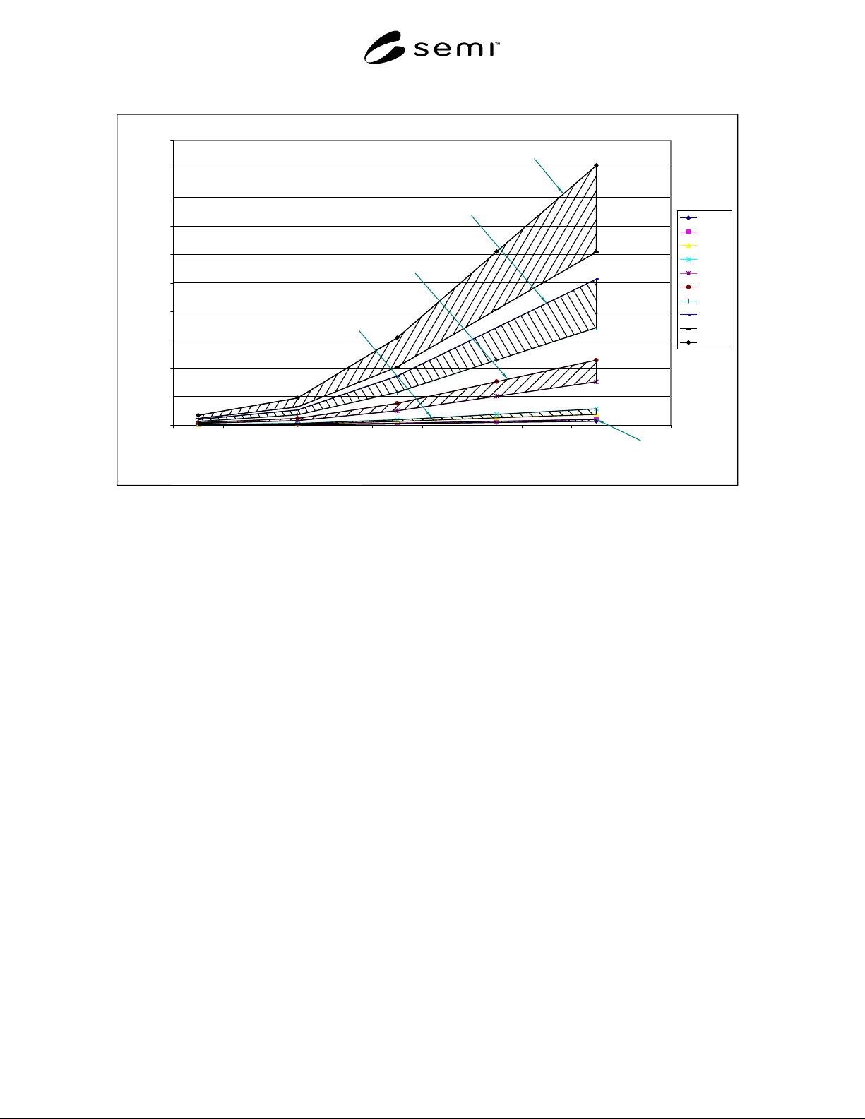
Figure 1 Nitrogen Flow Rate
0
200
400
600
800
1000
1200
1400
1600
1800
2000
700 2100 7000 14000 21000
Cylinder Pressure (kPa)
Nitrogen Flow Rate (slm)
0.15 lo
0.15 hi
0.25 lo
0.25 hi
0.50 lo
0.50 hi
0.75 lo
0.75 hi
1.00 lo
1.00 hi
1.00 mm equiv. orifice
0.75 mm equiv. orifice
0.50 mm equiv. orifice
0.25 mm equiv. orifice
0.15 mm equiv. orifice
Figure 1
Nitrogen Flow Rate
NOTICE: SEMI makes no warranties or representations as to the suitability of the standards set forth herein for any
particular application. The determination of the suitability of the standard is solely the responsibility of the user.
Users are cautioned to refer to manufacture's instructions, product labels, product data sheets, and other relevant
literature, respecting any materials or equipment mentioned herein. These standards are subject to change without
notice.
The user’s attention is called to the possibility that compliance with this standard may require use of copyrighted
material or of an invention covered by patent rights. By publication of this standard, SEMI takes no position
respecting the validity of any patent rights or copyrights asserted in connection with any item mentioned in this
standard. Users of this standard are expressly advised that determination of any such patent rights or copyrights, and
the risk of infringement of such rights, is entirely their own responsibility.
Copyright by SEMI® (Semiconductor Equipment and Materials
International), 3081 Zanker Road, San Jose, CA 95134. Reproduction o
f
the contents in whole or in part is forbidden without express written
consent of SEMI.