semi合集-English.pdf - 第6803页
SEMI S2-0703a E © SEMI 1991, 2004 32 Burton, D.J., IVE, Inc., Industrial Ventilatio n Workbook, 3rd Edition, 1995 , Lab Ventilation Workbook, 1994 ; 2974 South Oakwoo d, Bountiful, Utah 84010 NFPA 45, Fire Pro tection fo…
SEMI S2-0703a
E
© SEMI 1991, 2004 31
justification for when engineering controls are not
feasible to limit exposure during operation or
maintenance tasks, and how administrative controls
provide equivalent protection (see Section 26.2);
and
documentation showing compliance with an
appropriate international laser product safety or
industry standard, or the national standard for
country of use.
27 Sound Pressure Level
27.1 Equipment should be designed to control
exposures to sound pressure levels equal to or greater
than 80 dBA continuous or intermittent sound pressure
level, and 120 dB instantaneous (impulse) sound
pressure level.
NOTE 126: It is recommended that efforts be made to
decrease sound pressure levels as they approach 80 dBA (i.e.,
77 to 80 dBA), due to the additive sound pressure level effects
of multiple pieces of equipment in the same vicinity.
27.2 The order of preference for controlling exposures
is as follows:
27.2.1 Engineering Controls (e.g., source sound
pressure level reduction, absorption, enclosures,
barriers, acoustic dampening) — At a minimum, the
design of the engineering controls should consider the
sound pressure levels and type, the frequency, and the
appropriate control technologies.
27.2.2 Administrative Controls — Acceptable
administrative controls should be limited to
supplemental hazard warning labels and operating
procedures.
NOTE 127: Noise labeling is typically implemented as signs
located in the users facility.
27.3 Sound level surveys should be conducted by the
manufacturer during equipment development for
equipment that may emit hazardous sound pressure
levels.
27.3.1 The survey should be conducted in accordance
with a recognized standard. In addition, the following
test criteria should be applied:
27.3.1.1 The equipment mode of operation during the
sound pressure level tests should simulate as closely as
possible the actual modes and operating positions that
may be experienced by the equipment user.
27.3.1.2 Measurements should be taken in locations
that best simulate actual positions of operators relative
to the equipment. As a general guideline, the
microphone should be traversed 1 meter from the
equipment, 1.2 meters above the ground to simulate
seated operators, 1.5 meters above the ground to
simulate standing operators, and 3.5 meters (or as far as
possible) away from the nearest walls or sound-
reflecting objects. Measurements are taken 360 degrees
around the equipment wherever possible.
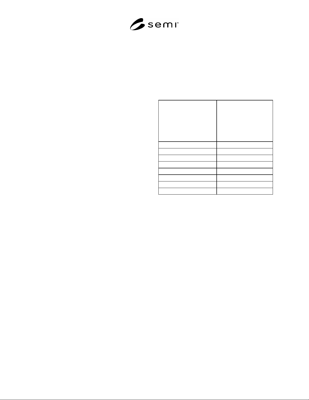
Table 2 Sound Pressure Level Test Criteria
NOTE 128: Background level may be subtracted using an
accepted method. If the sound pressure level difference is less
than 3 dBA, the contribution of the source from the
background cannot be adequately distinguished and the
survey results would not be valid for values over 80 dBA.
Difference between sound
pressure level measured
with noise source operating
and background sound
pressure level (dBA)
Correction to be subtracted
from the sound pressure
level measured with the
noise source operating to
obtain the sound pressure
level due to noise source
alone (dBA)
3 3
4 2.5
5 1.7
6 1.3
7 1
8 0.8
9 0.6
10 0.4
27.3.2 If the measured sound pressure level is less than
70 dBA, the manufacturer should provide to the
evaluator test data documenting sound pressure levels,
survey equipment, equipment calibration, test
conditions and results.
27.3.3 If the measured sound pressure level is greater
than 70 dBA, the test data should include all of the
information in Section 27.3.2, and should also include
the expected duration of personnel exposure.
27.3.4 If measured sound pressure level is greater than
75 dBA, information should be provided in the
equipment maintenance manual describing the sound
pressure level(s) and location(s).
28 Related Documents
28.1 The following documents are sources of
principles and practices of ventilation design.
ACGIH, Hazard Assessment and Control Technology
in Semiconductor Manufacturing, 1989, distributed by
Lewis Publishers, Chelsea, Michigan.
ANSI/AIHA, Standard Z9.5-1992 Laboratory
Ventilation
Burgess, Ellenbecker, Treitman, Ventilation for Control
of the Work Environment, John Wiley, NY, 1989

SEMI S2-0703a
E
© SEMI 1991, 2004 32
Burton, D.J., IVE, Inc., Industrial Ventilation
Workbook, 3rd Edition, 1995, Lab Ventilation
Workbook, 1994; 2974 South Oakwood, Bountiful,
Utah 84010
NFPA 45, Fire Protection for Laboratories Using
Chemicals, National Fire Protection Association, 1
Batterymarch Park, Quincy, MA, USA
Williams, M. and D.G. Baldwin, Semiconductor
Industrial Hygiene Handbook, Noyes Publications, Park
Ridge, NJ, 1995, ISBN 0-8155-1369-0
SEMI S2-0703a
E
© SEMI 1991, 2004 33
APPENDIX 1
ENCLOSURE OPENINGS
NOTICE: The material in this appendix is an official part of SEMI S2 and was approved by full letter ballot
procedures on December 15, 1999 by the North American Regional Standards Committee.
A1-1 This appendix provides guidance on sizes of
openings in enclosures.
Table A1-1 Examples of Openings for Protection
Against Access from Operators
Distance Between Opening
and Danger Point
Maximum Opening
mm inches mm inches
13–38 0.5–1.5 6 0.250
38–64 1.5–2.5 10 0.375
64–89 2.5–3.5 11.9 0.470
89–140 3.5–5.5 16 0.625
140–165 5.5–6.5 19 0.750
165–191 6.5–7.5 22 0.875
A1-1.1 Alternatively, an IEC accessibility probe, as
specified in SEMI S9, may be used to determine
suitability of mesh openings.
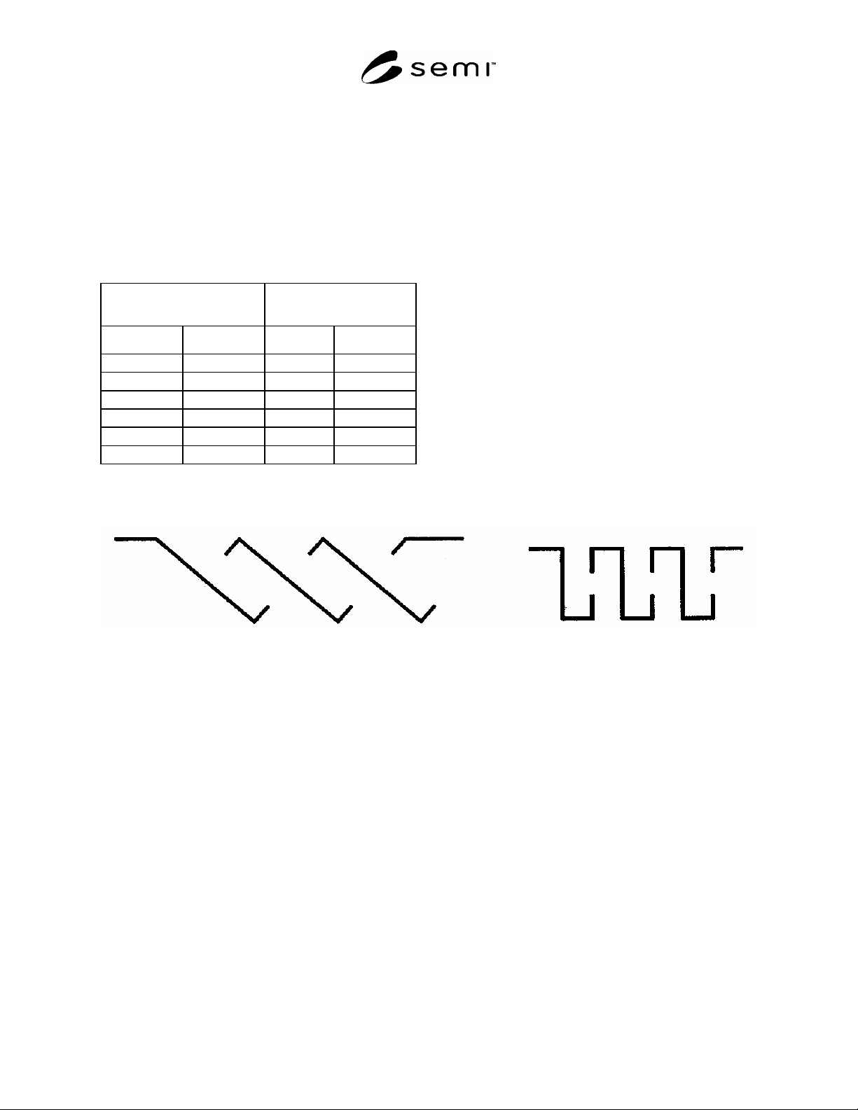
A1-2 Top Openings in Electrical Enclosures — The
top openings in electrical enclosures should meet one of
the following:
not exceed 5 mm in any dimension, or
not exceed 1 mm in width regardless of length, or
be so constructed that direct, vertical entry of a
falling object is prevented from reaching
uninsulated live parts within the enclosure by
means of trap or restriction (see Figure A1-1 below
for examples of top cover designs that prevent such
direct entry), or
meet the intent through other equivalent means.
Figure A1-1
SLANTED OPENINGS VERTICAL OPENINGS