semi合集-English.pdf - 第2115页
SEMI E54.14-0305 © SEMI 2005 9 6.9.4 Communication Management 6.9.4.1 DCP (Discovery and Confi guration Prot ocol) is used for basic ma nagement of stati ons (especially setting of IP-address an d Device name). DHCP (Dyn…
SEMI E54.14-0305 © SEMI 2005 8
sending of alarms to IO devices
6.9.3 Protocol Specification
6.9.3.1 An IO device has no IP-address and logical name when it is shipped.
6.9.3.2 A set up procedure has to allocate name and IP-address prior to operation.
6.9.3.3 To access an IO Device a controller has to establish the context first with a connect service. A check is
done to ensure that the appropriate device type with the required resources is accessed. Resources can be locked
with the connect service.
6.9.3.4 After a positive confirmation of the connect service the IO device may be loaded with the parameter
required by the controller application (e.g. warning limits, measure range, filter time). A control service is issued at
the end of parameterization.
6.9.3.5 There is a control service indicating that the IO Device application is ready to enter the operate state. The
start up is completed with this service.
6.9.3.6 After this start up procedure the data exchange of IO data can be done and alarms can be signaled from the
IO Device to the IO Controller. The IO Controller can invoke services to read and write record data that contain all
kind of information e.g. produced units, calibration information, and batch information.
6.9.3.7 A Release service will terminate the context.
6.9.3.8 A context is monitored by the receipt of Input Data at the IO controller and by the receipt of Output Data at
the IO device site. A timeout error of one timer unit is allowed which makes it possible to use a single timer
resource with granularity in the range of a millisecond.
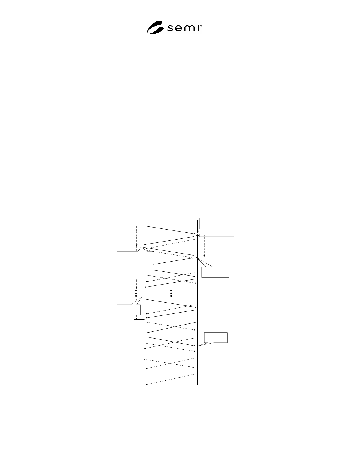
6.9.3.9 Figure 3 shows a sequence diagram of the start up procedure.
IO Controller
IO Device
CM_Connect.req()
CM_Connect.rsp (+)
Write_Record.req()
Write_Record.rsp (+)
IO Controller-
Timeout
Establish
Provider/Consumer/
Alarm-Statemachine
Start Provider
Start Consumer
with Monitoring
Write_Record.req()
Write_Record.rsp (+)
CControl.req()
CControlrsp()
Outputs
Inputs
DControl.req()
DControl.rsp(+)
Start Alarm-
Statemachine
Start Alarm-
Statemachine
Establish
Provider/Consumer/
Alarm- Statemachine
Start Provider
Start Consumer with
Monitoring
Figure 3
Start Up Sequence
SEMI E54.14-0305 © SEMI 2005 9
6.9.4 Communication Management
6.9.4.1 DCP (Discovery and Configuration Protocol) is used for basic management of stations (especially setting of
IP-address and Device name). DHCP (Dynamic Host Configuration Protocol) can be used as configuration option.
6.9.4.2 Connectionless DCE RPC is used as an interface between transport and application.
6.9.4.3 “Identification & Maintenance Functions” (I&M functions) define general parameters and protocols. The
main purpose of the I&M functions is to support the end user during various scenarios of a device’s life cycle be it
configuration, commissioning, parameterization, diagnosis, repair, firmware update, asset management, audit
trailing, and alike. Well-defined uniform parameters and rules should enable the manufacturers to offer devices that
behave in a uniform manner These profile guidelines take into account requirements from FDA (Food & Drug
Administration) and others. The basic information offered can be characterized as “Type Plate” or “Boiler Plate”. It
consists of Manufacturer ID, Order ID, Serial Number, Hardware Revision, Software Revision, Revision Counter,
Profile ID.
7 Required Object Types
7.1 This section describes a general mapping of the SEMI SAN Object Model to the PROFINET environment.
Component definitions are clarified and the mapping of Attributes, Services, and Behaviors are specified.
7.2 Object Model
7.2.1 The Object Model defined in the CDM is represented in the PROFINET NCS. Specifically, the DM and SAC
objects are mapped.
7.2.2 The CDM Objects are mapped to slots. These slots have a unique address space within the device. The
Specific Application Objects are mapped in PROFINET Device Data Base. §9 specifies the mapping of SDM
Objects in PROFINET.
7.3 Component Mapping Summary
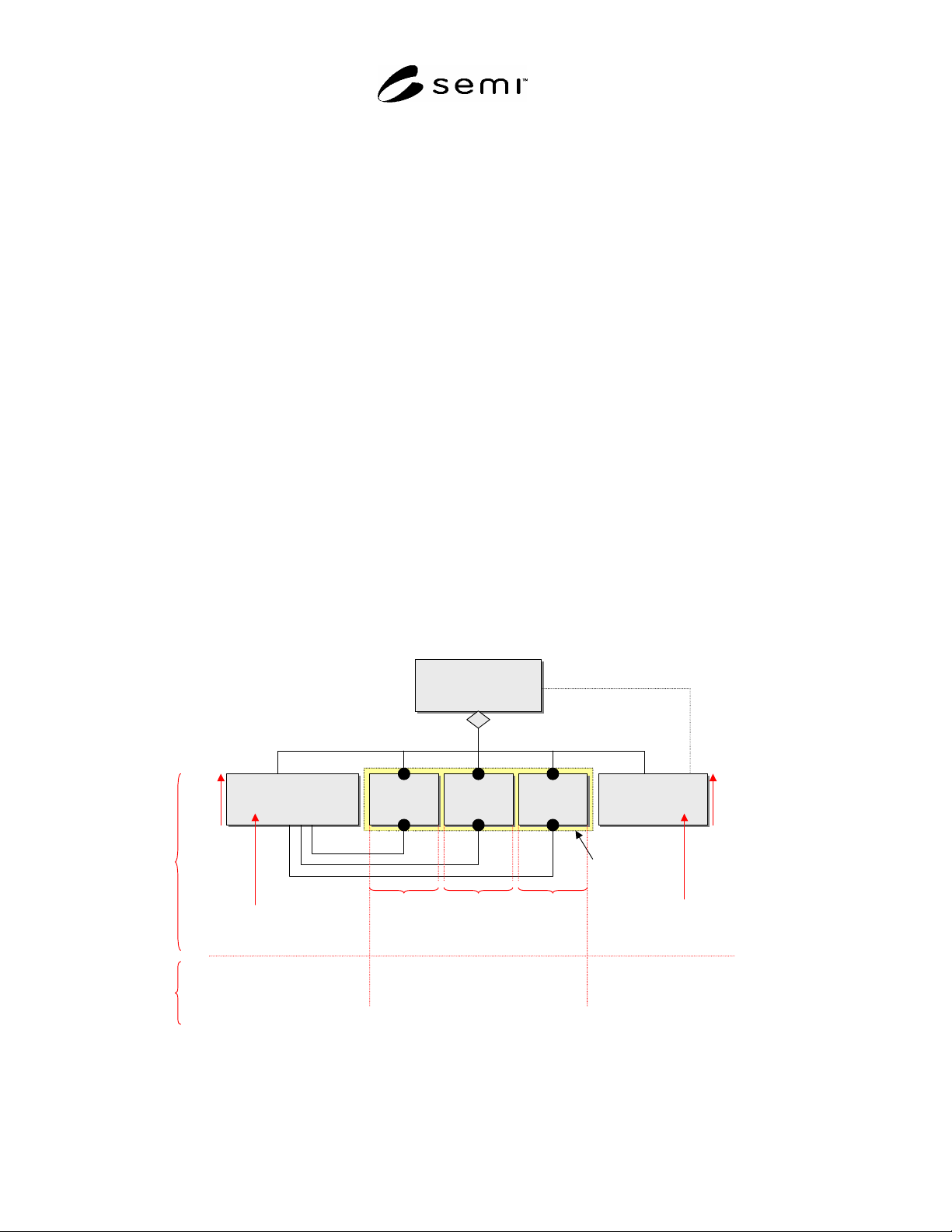
7.3.1 Figure 4 provides a summary of the components of the CDM object model as they relate to the components of
PROFINET.
Device
Device
Sensor/Actuator/
Controller Object
(SAC)
Sensor/Actuator/
Controller Object
(SAC)
Sensor
Object(s)
Sensor
Object(s)
Actuator
Object(s)
Actuator
Object(s)
Controller
Object(s)
Controller
Object(s)
Device Manager
Object
(DM)
Device Manager
Object
(DM)
is managed by
(Aggregation)
coordinates
m + n + p * 1
mn p
mn p
Active Element
Slot 0
Slot 0
1 Slot
per object,
starting with
Slot 1
1 Slot
per object,
starting with
Slot m+1
1 Slot
per object,
starting with
Slot m+n+1
Index
64
95
other Services
Cyclic
Services
Cyclic Data Structures will
be defined by Device Families
(Profiles) and via GSD
Figure 4
Component Mapping Summary
SEMI E54.14-0305 © SEMI 2005 10
7.4 Objects
7.4.1 The required objects of the CDM are identified here. Additional objects that are contained in the SDM are
given identifiers in the Device Profile. §9 specifies
additional mapping information.
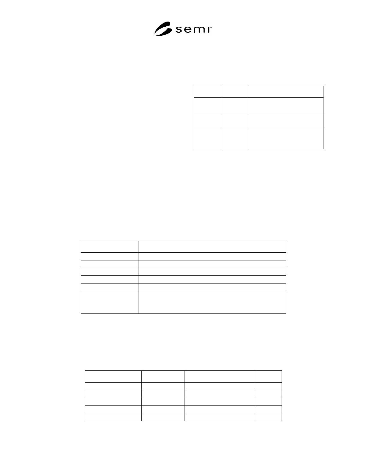
7.4.2 Table 2 lists the Object Identifiers specified for use
in protocol messages. Slot numbers is the mechanism
used for addressing Objects within PROFINET. Subslot
IDs can be used for sub addressing. Within this NCS the
subslot 1 shall be used as default subslot.
7.4.3 Assembly Objects and Local Link Objects which
are objects embedded in the SAC Object are not explicitly
mapped in PROFINET.
7.5 Attributes
7.5.1 General
7.5.1.1 All attributes are accessible via Get_Attribute and
Set_Attribute services defined in the sections below. The Get_Attribute and Set_Attribute services shall be mapped
to PROFINET Read and Write services for Record Data objects. Additionally, attributes are accessible via different
PROFINET defined methods that are mapped in this document based on attribute type.
7.5.2 DM Attributes
7.5.2.1 All attributes are communicated with Read and Write Service and mapped to IM Blocks. Status attributes
are modeled additionally as Diagnosis. See Table 17 for detailed mapping.
7.5.2.2 Table 3 shows the DM status attribute mapping to Diagnosis.
Table 3 Diagnosis Mapping of DM Status
Parameter Value
Slot 0 = Device
Subslot 1 = Device
Channel 0 = Global
Channel Type 0 = unspecified
IO Type 0 = unspecified
Error Type 9 = Error with Bit0 - 6 set in Common Exception Detail 1
21 = Error Calibration set in Common Exception Detail Attribute 1
17 = Error with Bit set in Common Exception Detail 2
7.5.3 SAC Attributes
7.5.3.1 The attributes of SAC are mapped to Record data objects of PROFINET.
7.5.3.2 The Slot number used is 0. The index is the numeric value of the SAC Attribute identifier with an offset of
64 (see Table 4).
Table 4 SAC Object Attribute Identifiers
SEMI CDM Attribute ID PROFINET Index Attribute Detail
SacA1 65 Last Calibration Date
SacA2 66 Next Calibration Date
SacA3 67 Expiration Timer
SacA4 68 Expiration Warning Enable
SacA5 69 Run Hours
Table 2 Object Identifiers
Slot ID Index Object
0 IM0-17
96
DM Object Attributes
DM Control
0 64
65-95
SAC Control
SAC Object Attributes
1–z 64
65-254
Application Object Control
Application Objects Attributes as
specified in §7 and §9