semi合集-English.pdf - 第2133页
SEMI E54.15-0305 © SEMI 2005 5 SafetyBUS p OCS documentation. In addition the device shall comply with the object specificatio ns defined in §7 of this docum ent. 6.9 Net work Management — The device shall com ply with t…
SEMI E54.15-0305 © SEMI 2005 4
6 Communication Protocol High Level Structure
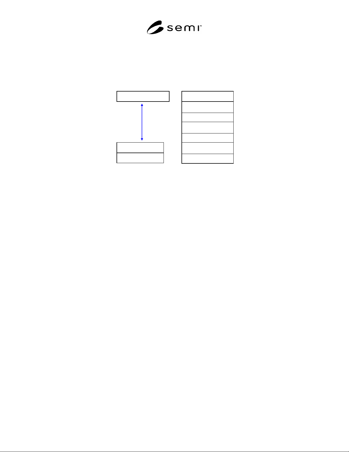
6.1 The SafetyBUS p protocol is loosely based on three layer architecture. These three layers constitute a collapsed
form of the seven layer OSI architecture which map into the physical, data link, and application layers of the OSI
Basic Reference Model (see ¶4.2). The high-level protocol architecture is shown in Figure 1.
Application Layer
Physical Layer
Data Link Layer
Physical Layer
Data Link Layer
Network Layer
Transport Layer
Session Layer
Presentation Layer
Application Layer
Layered View of SafetyBUS p
OSI Reference Model
Figure 1
Layered View of SafetyBUS p
6.1.1 Note that Figure 1 represents a conceptual view of the technology architecture. Conforming implementations
must implement the services defined in this specification at each layer and must appear (from the network) to have
implemented this architecture, however an internal modular partitioning is not required. Implementations may
sacrifice modularity in order to achieve high performance.
6.1.2 The application layer is specified in the SafetyBUS p OCS (see reference ¶4.3) and provides for the definition
of SafetyBUS p applications as a collection of addressable objects. A subset of these objects may be addressed over
the network (as defined by the implementation).
6.1.3 In the remainder of this section the protocol structure is described in more detail in terms of the OSI seven
layer reference model, the object model environment and network management specifications.
6.2 Physical Layer — The device shall comply with a physical layer specification identified in the Controller Area
Network (CAN) specification. Physical layer specification includes physical signaling (levels and data rates),
transceivers, node isolation, media topology, cable specifications, network connectors and taps, and power
considerations (load limits, system tolerances, and power supply options).
6.3 Data Link Layer — The device shall comply with a data link layer specification the Controller Area Network
(CAN) specification. Data link layer specification includes the media access control mechanism and the logical link
control mechanism.
6.4 Network Layer — There is no distinct Network layer.
6.5 Transport (Messaging) Layer — There is no distinct Transport layer.
6.6 Session Layer — There is no distinct Session layer.
6.7 Presentation Layer — There is no distinct Presentation layer.
6.8 Application Layer — The device shall comply with the SafetyBUS p application layer specification for defining
and addressing objects, including their attributes and services, and enabling specified network behavior. The device
shall comply with the object messaging and object model specifications included in the SafetyBUS p OCS. In
addition the device shall comply with the object specifications defined in §7 of this document.
6.8.1 Object Models — The SafetyBUS p protocol includes an object-oriented specification for addressing objects
explicitly, including their attributes and services, and communicating object attributes in an application dependent
format. The device shall comply with the object messaging and object model specifications included in the
SEMI E54.15-0305 © SEMI 2005 5
SafetyBUS p OCS documentation. In addition the device shall comply with the object specifications defined in §7
of this document.
6.9 Network Management — The device shall comply with the SafetyBUS p and CAN network management
specifications detailed in the SafetyBUS p standard and SafetyBUS p Guide to Programmable Safety Systems
Standard Specifications (e.g., physical layer bit rate, master/slave and peer-to-peer network management, etc.). No
(additional) network management functions are specified in this document.
7 Required And Optional Object Types
7.1 The SafetyBUS p standard specification does not require any specific objects to exist in a SafetyBUS p device
in order to be a compliant SafetyBUS p device. The SafetyBUS p standard specification is extended in this standard
to identify and describe objects (i.e. classes) that shall exist in devices that are to be interoperable and
interchangeable on a SafetyBUS p SEMI compliant SAN network.
7.1.1 The Common Device Model (CDM) specification (see reference SEMI E54.1 ¶4.1) identifies two objects
(namely the Device Manager (DM) and Sensor Actuator Controller (SAC) objects) that shall exist in all SEMI
compliant SAN devices.
7.1.2 The required object types for a SEMI compliant SAN device utilizing the network communication
specification described herein necessarily comprises, at minimum, the union of the SafetyBUS p object type
requirements and the CDM specification requirements.
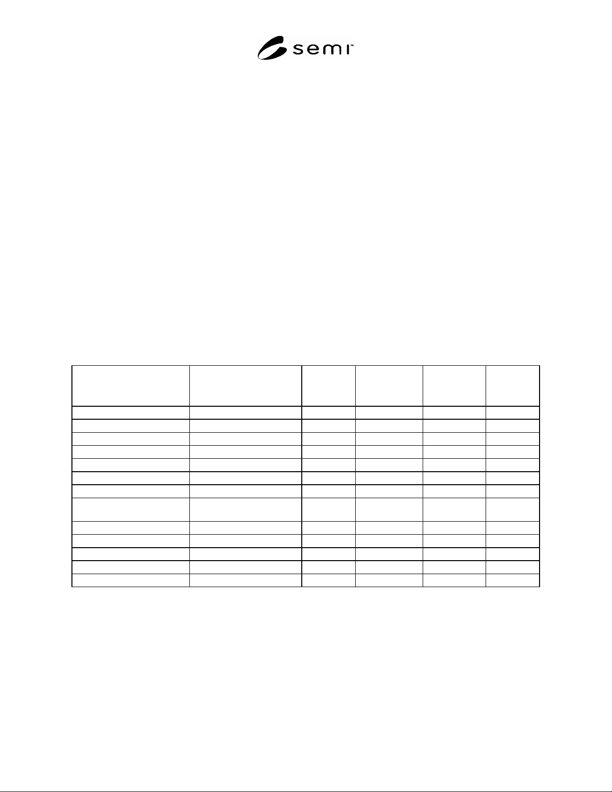
7.1.3 A list of required and optional object types is given in Table 2. Additional objects that are specified in a
particular SDM are given identifiers in that SDM specification; SafetyBUS p specific presentation information for
these identifiers is given in Section 9 of this document.
Table 2 Required and Optional Object Types
Object Name SafetyBUS p
Class ID / Instance ID
#1
CDM Tag
#2
Required by
SafetyBUS p
#1
Required by
CDM
#2
Required
by NCS
Device Manager 1/1 DmI0 No Yes Yes
Sensor/ Actuator/ Controller 2/1 SacI0 No Yes Yes
Assembly 3/1 through i Asm No No No
Local Link 4/1 through j Lnk No No No
Sensor – AI 33/1 through k Sai No No No
Sensor – EI 34/1 through l Sei No No No
Sensor – BI 35/1 through m Sbi No No No
Actuator – AO 36/1 through n Aao No No No
Actuator – EO 37/1 through o Aeo No No No
Actuator – BO 38/1 through p Abo No No No
Controller 39/1 through q C No No No
Sensor – BI-TH 40/I through s Sbith No No No
Application Objects 129 through x/1 through r (3) No No No
#1
See SafetyBUS p specification for further information; values are decimal; ‘i’, ‘j’, ‘k’, ‘l’, ‘m’, ‘n’, ‘o’, ‘p’, ‘q’, ‘r’ and ‘s’ represent arbitrary
numbers (greater than or equal to 1) indicating that more than one instance may be supported. ‘x’ is a number greater than or equal to 129
indicating that one or more application object classes may be supported.
#2
See CDM specification for further information
#3
Application Dependent objects’ tags as specified in SDM
7.1.4 An embodiment of a specific device type represented as an aggregation of the object types listed in Table 2
that is compliant with both the CDM specification and the SafetyBUS p specification, is a candidate for a SEMI
SDM as well as a SafetyBUS p device definition. Conversely, all SEMI SDMs and SafetyBUS p device definitions
specified for operation over a SEMI compliant SafetyBUS p network must be an aggregation of the object types
listed in Table 2, and be compliant with both the CDM specification and the SafetyBUS p standard specifications.

SEMI E54.15-0305 © SEMI 2005 6
7.1.5 In the following sections the presentation to the network of object addressing, object attributes and object
services for each of the object types listed in Table 2 is described in detail. Refer to the CDM standard to determine
if the object instance attribute and service is specified as required or optional. Unless otherwise noted, all attributes
and services described are instance level attributes (as opposed to class level attributes). A class level attribute and
service is accessed as instance number zero.
7.1.6 Note that the formats of object attributes and services are detailed in the CDM document; the presentation of
object attributes and services to the SafetyBUS p network is detailed in the tables contained in the following sub-
sections and in the SafetyBUS p standard specifications.
7.2 Device Manager (DM) Object –– The DM object instance is the device component responsible for managing
and consolidating the device operation. Each device must support one (and only one) DM object. The DM object as
well as its common required and optional attributes, services and behavior are described in the CDM standard. The
presentation of object instance attributes and services to the SafetyBUS p network shall be as indicated in Table 3.
Note that all service ID values identified refer to the ID of the request or notification component of that service.
Corresponding reply components to request/reply services shall have a service ID value equal to the request
component ID plus one.
Table 3 DM Object Instance Attributes and Services
Device Manager Object (DM)
Class ID = 01, Instance ID = 01
Attributes
ID Attribute Name CDM Tag
01 Device Type DmA1
02 Standard Revision Level DmA2
03 Device Manufacturer Identifier DmA3
04 Manufacturer Model Number DmA4
05 Software or Firmware Revision Level DmA5
06 Hardware Revision Level DmA6
07 Serial Number DmA7
08 Device Configuration DmA8
09 Device Status DmA9
10 Reporting Mode DmA10
11 Exception Status Report DmA11
12 Exception Status DmA12
13 Exception Detail Alarm DmA13
14 Exception Detail Warning DmA14
15 Visual Indicator DmA15
16 Alarm Enable DmA16
17 Warning Enable DmA17
18 Exception Detail Type DmA18
19 Exception Detail Alarm Queue DmA19
20 Exception Detail Warning Queue DmA20
21 Date and Time DmA21
22 Date and Time Type DmA22