semi合集-English.pdf - 第788页
SEMI E106-1104 © SEMI 2000, 2004 6 interbay load ports), by SEMI E15.1 (for its manual/AGV/ RGV load ports), by SEMI E8 5 (for its interbay load ports), b y SEMI E84 (for its carrier handoff parall el I/O at either kind …
SEMI E106-1104 © SEMI 2000, 2004 5
6.3 Wafer Carriers — SEMI E1.9 and SEMI E47.1
specify the carriers used to transport and store 300 mm
wafers in an IC manufacturing facility. SEMI E47.1
specifies the outside features of the front-opening
unified pod (FOUP). The inside features of the FOUP
are specified in SEMI E1.9, which also specifies the
open cassette. Both standards specify carriers that hold
either 13 or 25 wafers. SEMI M31 specifies the front-
opening shipping box (FOSB) used to transport and
ship 300 mm wafers. SEMI E103 specifies a system
that includes a box that holds only one wafer and that
fits onto an adapter mechanism called a single-wafer
interface (SWIF). This system appears to the
equipment to be a 300 mm FOUP (except that only the
volume around the middle wafer may be accessible).
6.4 Equipment Load Ports — SEMI E15.1 specifies
the carrier load ports at the front of 300 mm process or
metrology equipment (or stockers). In addition, the
substrate port that opens a FOUP door is specified in
SEMI E62 (FIMS). At the floor below each load port is
a cart docking interface exclusion volume specified in
SEMI E64; this volume can contain a PGV docking
flange as specified in SEMI E83. SEMI E63 (BOLTS-
M) or SEMI E92 (BOLTS-Light) or both standards
specify the mechanical interface between the main part
of a process or metrology tool and the box
opener/loader unit that opens FOUPs and presents them
to the tool wafer handler for unloading and loading 300
mm wafers. Also associated with each load port is a
wire or optical link (from the equipment to the AMHS
carrier delivery system) specified in SEMI E84 which
is the 300 mm version of SEMI E23. SEMI E99 and
SEMI E99.1 specify the electronics and communication
interface between a carrier ID reader/writer and the
equipment controller. SEMI E101 specifies the
functional structure model and component behavior for
the entire equipment front-end module (EFEM). SEMI
E110 specifies the placement of indicators and switch.
6.5 Cluster-Tools — SEMI standards for 300 mm
cluster tools include SEMI E22.1, SEMI E21.1, SEMI
E26.1, and SEMI E25.
6.6 AMHS — SEMI standards for automated material
handling systems (AMHS) include SEMI E85.
6.7 Equipment Volume and Weight — SEMI E72
specifies limits on the footprint, height, and weight of
equipment for 300 mm fabs. Separate limits are given
for the parts of the equipment in the main fab and in the
sub-fab. Separate limits are also given for the
equipment after it is installed and for the components of
the equipment as it is moved into the fab.
6.8 Back-End Standards — SEMI G74 specifies the
tape frames used for 300 mm wafers between the dicing
process and the die-bonding process. SEMI G77
specifies the mechanical features of a metal or plastic
frame cassette used for framed 300 mm wafers between
the wafer mounting process and the die-bonding
process. Future standards may also specify the carrier
for thinned 300 mm wafers and the load port for back-
end process or metrology equipment.
6.9 Standards of Uncertain Use — Some SEMI 300
mm standards that passed balloting have a scope of
application or extent of use that is yet to be fully
determined. Such standards include SEMI M29 which
specifies a manually-opening shipping box for 300 mm
wafers. In the other SEMI 300 mm standards are also
some options of uncertain use such as bottom-opening
pods and pods with removable cassettes.
7 Application of Standards to Products
7.1 One-Sided Interface Specifications — The SEMI
standards for 300 mm physical interfaces and carriers
are intended to set an appropriate level of specification
that places minimal limits on innovation while ensuring
modularity and inter-changeability between different
types of products. To accomplish this, only one side of
each mechanical interface (between different types of
products) is specified, leaving the supplier of the
product on the other side of the interface more freedom
to improve their product. For example, only the bottom
half of the kinematic coupling (the pin) is specified by
SEMI E57 so that suppliers can be flexible in designing
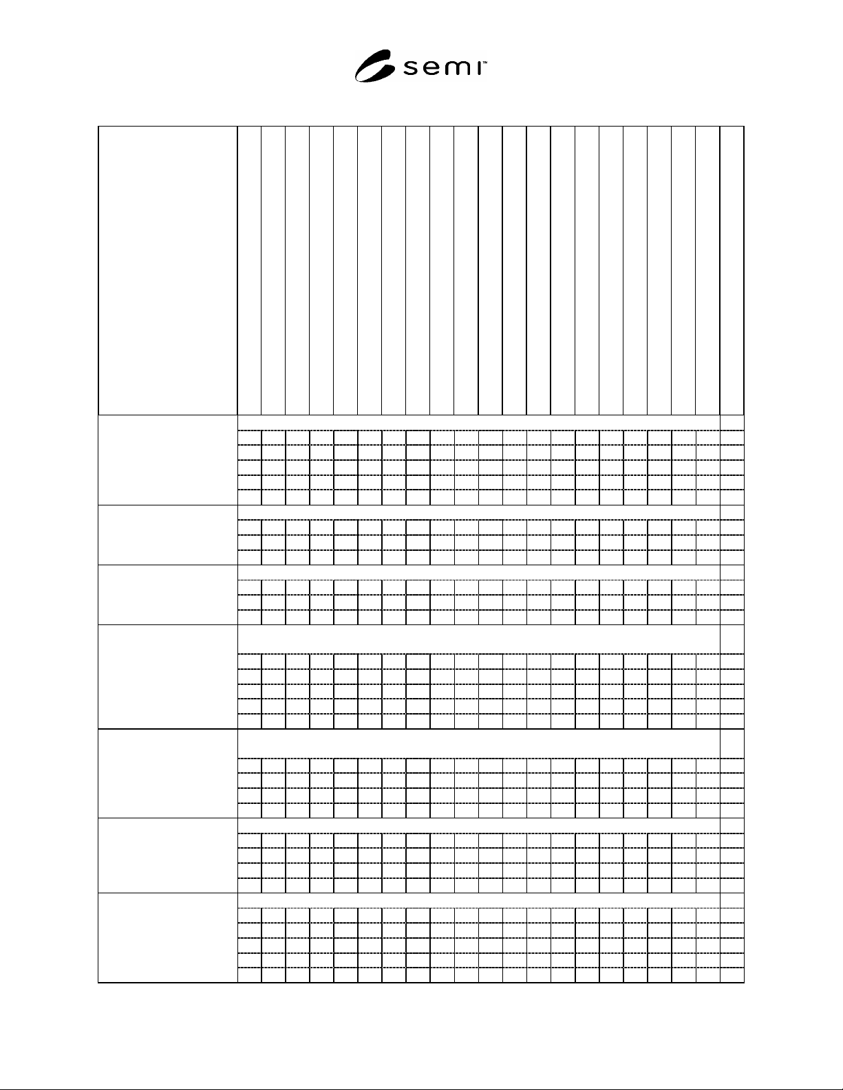
wafer carrier grooves that can mate with it. Table 1
shows which standards apply to each type of product
and shows which side of the interface is specified:
“D” indicates if the standard directly specifies that
type of product (by specifying that product’s side
of the relevant interface).
“I” indicates if the standard indirectly specifies that
type of product (by specifying the other side of the
relevant interface).
7.2 Carriers — A FOUP is directly specified by SEMI
E47.1 (for its outside features not including the door)
and by SEMI E1.9 (for its inside features). The FOUP
is indirectly specified by SEMI E57 (for its kinematic
coupling grooves) and by SEMI E62 (for its FIMS door
interface). Thus, if a FOUP door fails to open or close
correctly on any load port that complies with SEMI E57
and SEMI E62, that FOUP is in violation of the
standards. The wafer support function of all of the 300
mm carriers is specified directly (by specifying where
the wafers must be located rather than specifying the
shape and location of the supports), so the 300 mm
wafer standards indirectly specify the carriers.
7.3 Stockers — A carrier stocker is directly specified
by SEMI E57 (for the kinematic coupling pins on its
shelves, if any, and on its manual/AGV/RGV and

SEMI E106-1104 © SEMI 2000, 2004 6
interbay load ports), by SEMI E15.1 (for its
manual/AGV/RGV load ports), by SEMI E85 (for its
interbay load ports), by SEMI E84 (for its carrier
handoff parallel I/O at either kind of load port) and by
SEMI E64 (for the cart docking interface exclusion
volume below each manual/AGV/RGV load port). The
carrier stocker is indirectly specified by the carrier
standards (for the volume required to store and transfer
the carriers).
7.4 Carrier ID — A carrier ID reader/writer unit is
directly specified by a future standard that specifies the
electronics and communication interface between a
carrier ID reader/writer and the equipment controller.
The carrier ID reader/writer unit is indirectly specified
by the carrier standards (which specify reserved areas
for carrier ID tags) and by SEMI E15.1 (for its
exclusion volume in each load port).
7.5 Load Port and Carrier Handler Modules — A box
opener/loader (the module on a piece of equipment that
includes load ports and carrier handling) is directly
specified by SEMI E57 (for the kinematic coupling pins
on the load port and on its shelves if it includes an
internal buffer in addition to its fixed buffer), by SEMI
E15.1 (for its load ports), by SEMI E62 (for its FIMS
door interface), by SEMI E84 (for its carrier handoff
parallel I/O), by SEMI E64 (for the cart docking
interface exclusion volume below each load port), by
SEMI E72 (for its limits on footprint, height, and
weight), and by SEMI E110 (for indicator/switch
placement). The module is indirectly specified by the
carrier standards (for the volume required to store and
transfer the carriers) and by SEMI E63 and/or SEMI
E92 (for the mechanical interface to the main part of the
process or metrology equipment that contains the
substrate handler).
7.6 Main Part of Process or Metrology Equipment —
The main part of process or metrology equipment
(including the substrate handler) is directly specified by
SEMI E63 and/or SEMI E92 (for the mechanical
interface to the module that includes load ports and
carrier handling) and by SEMI E72 (for its limits on
footprint, height, and weight). The substrate handler is
indirectly specified by SEMI E1.9 (for the features
inside most carriers) and it is recommended to follow
the direct specifications in SEMI E22.1 (which
specifies cluster-tool end effectors).
7.7 Material Handling Systems — A carrier transport
vehicle is directly specified by SEMI E57 (for the
kinematic coupling pins on the carrier nest, if any) and
by SEMI E84 (for its carrier handoff parallel I/O, if
any). The AMHS system is indirectly specified by the
carrier standards (for the volume required to hold and
transfer the carriers), by SEMI E15.1 (for equipment
load ports), by SEMI E85 (for stocker load ports, if it is
an OHT), by SEMI E72 (to allow for equipment height,
if it is an OHT), and by SEMI E64 and SEMI E83 (for
the cart docking interface exclusion volume and the
PGV docking flange, respectively, below each
equipment load port, if it is a floor based vehicle).
SEMI E106-1104 © SEMI 2000, 2004 7
Table 1 Standards Specifying Each Type of Product (D = Direct Specification, I = Indirect Specification)
Type of Product and its
Components
SEMI M1.15, M8, or M28 (Wafer)
SEMI E57 (Kinematic Coupling)
SEMI E1.9 (Cassette)
SEMI E47.1 (FOUP)
SEMI M31 (FOSB)
SEMI E103 (Single-Wafer Box System)
SEMI E62 (FIMS)
SEMI E63 (BOLTS-M) and/or E92 (BOLTS-Light)
SEMI E15.1 (Load Port)
SEMI E64 (Cart Docking Interface)
SEMI E83 (PGV Docking Flange)
SEMI E84 (Carrier Handoff Parallel I/O)
SEMI E99 & E99.1 (Carrier ID Reader/Writer Comm.)
SEMI E85 (Stocker to Interbay Transport System)
SEMI E22.1 (Cluster- Tool End Effector)
SEMI E21.1 (Cluster-Tool Module Interface)
SEMI E25 & E26.1 (Cluster-Tool Access & Footprint)
SEMI E72 (Equipment Footprint, Height, and Weight)
SEMI G74 (Tape Frame)
SEMI G77 (Frame Cassette)
SEMI E110 (Indicator/Switch Placement)
FOUP:
wafer supports I
coupling grooves I
inside features D D
outside features D
door D I
open cassette:
wafer supports I
coupling grooves I
other features D
shipping box:
wafer supports I
coupling grooves I
other features D
single-wafer box and
SWIF system:
wafer supports I
coupling grooves I
inside features D D D
outside features D D
door D D I
interbay transport
vehicle:
carrier supports D
carrier envelope I I
hand-off I/O I D
stocker load ports I
roller conveyor:
carrier rails I I
carrier envelope I I
equipment load ports I
hand-off I/O D
PGV:
carrier supports D
carrier envelope I I
carrier handler I I I
tool load port access I I
docking features I I