semi合集-English.pdf - 第4120页
SEMI F61-0301 © SEMI 2001 5 Feed Water ≤ ≤ ≤ ≤ 5 µ µ µ µ ≤ ≤ ≤ ≤ 1 µ µ µ µ ≤ ≤ ≤ ≤ 1 µ µ µ µ ≤ ≤ ≤ ≤ 0.02 µ µ µ µ Figure 1 Schematic of a Typical Ultrapure Water System NOTICE: SEMI makes no warranties or representations…

SEMI F61-0301 © SEMI 2001 4
be configured in a double-pass arrangement consisting
of two RO membrane units in series. Permeate
(filtered water) from the first RO unit is sent to the
second RO unit to be filtered again. It is not
uncommon for the permeate from a double-pass RO
unit to have a resistivity reading up to 0.5–4 Megohm-
cm, with less than one milligram per liter of organic
and silica contaminants. The more contaminants
removed in the membrane treatment step, the lower the
loading on the Polishing steps.
7.3 Volatiles Removal The removal of dissolved
oxygen, carbon dioxide, other gases, and volatile
organic compounds is a necessary treatment step. The
removal of these volatile contaminants is accomplished
to acceptable levels in vacuum degasifiers and in
membrane degasification units. The removal of
volatiles that can form ions and the removal of volatile
organic compounds reduce the loading on downstream
Polishing equipment.
7.4 Polishing The relatively low level of
contaminants that were not removed in the Membrane
Treatment and Volatiles Removal steps are polished
down to acceptable levels in the Polishing steps. Ionic,
organic, and silica contaminants are removed in
typically two stages of Ion Exchange in series (primary
beds and polishing beds). Organic compounds,
measured as TOC (Total Organic Carbon, or Total
Oxidizable Carbon), that are found downstream of the
RO membrane units may be subjected to TOC
Reduction ultraviolet (UV) irradiation (185 nanometer
low pressure units or medium pressure units) to convert
most of them into ionic compounds that can be
effectively removed by Primary Ion Exchange Units
(usually consisting of Separate Beds, Mixed Beds or
EDI/CDI/E-Cell). TOC compounds that exit the
primary ion exchange units are typically subjected to
TOC reducing UV irradiation to break them into
ionized compounds to be removed by the Polishing Ion
Exchange Units. The vast majority of all living
suspended particles (mainly bacteria) that enter any 254
nm UV unit are inactivated. Downstream filters with a
pore size of less than or equal to 0.45 micron remove
the inactivated bacterial bodies. The final filter prior to
Distribution typically has a pore size of less than 0.2
micron.
8 Distribution
8.1 Distribution is frequently comp osed of one or
more Loops. Each loop consists of UPW that
continuously recirculates through appropriate piping
from the final filters, to the manufacturing areas
requiring UPW (end users), and back to a tank located
within the Polishing section to be polished again. The
UPW to the end-user area is commonly called the
Supply. The UPW that travels from the end-user area
back to the water treatment area is commonly called the
Return. Ozone may be injected into the Supply and/or
Return line to control microbiological contaminants and
also to enhance the action of TOC breakdown in
downstream TOC reducing UV units. Sometimes ozone
is injected into the Supply line for similar reasons
(requires de-ozonation at the end-use points).
Sometimes the UPW in the distribution loop is heated
(hot loop) for particular processes.
8.2 Basic System Components
8.3 General Each UPW system contains certain
basic components and a variety of design options to
meet particular customer and facility needs. An
example of a UPW system is shown in Figure 1
attached.
9 Related Documents
9.1 SEMI Standards
SEMI F4 — Guide for Standard Performance,
Practices, and Sub-Assembly for High Purity Piping
Systems and Final Assembly for Semiconductor
Manufacturing Equipment
SEMI F31 — Guide for Bulk Chemical Distribution
Systems
SEMI S2 — Environmental, Health, and Safety
Guideline for Semiconductor Manufacturing Equipment
9.2 SIA
1
National Technology Roadmap For Process Chemicals
1 Semiconductor Industry Association, 181 Metro Drive, Ste 150, San
Jose, CA 95110, USA
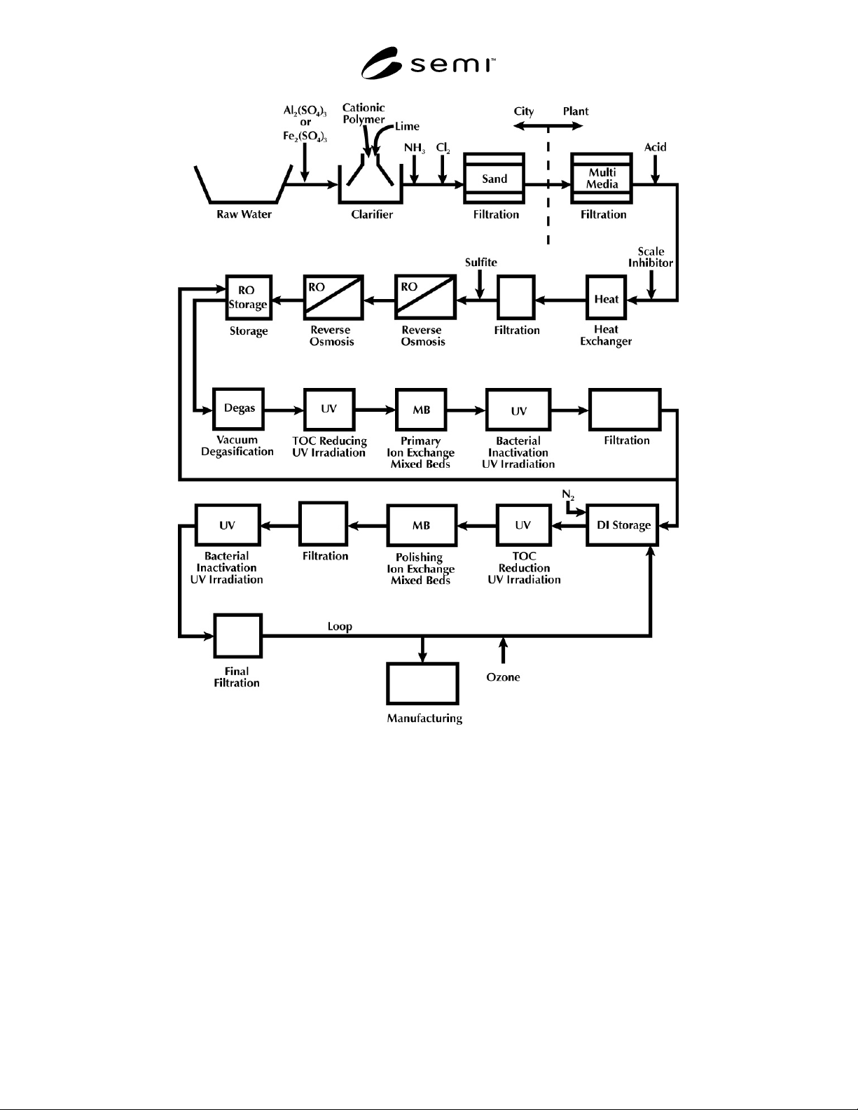
SEMI F61-0301 © SEMI 20015
Feed
Water
≤
≤
≤
≤ 5
µ
µµ
µ
≤
≤≤
≤ 1
µ
µµ
µ
≤
≤
≤
≤ 1
µ
µµ
µ
≤
≤
≤
≤ 0.02
µ
µµ
µ
Figure 1
Schematic of a Typical Ultrapure Water System
NOTICE: SEMI makes no warranties or representations as to the suitability of the standards set forth herein for any
particular application. The determination of the suitability of the standard is solely the responsibility of the user.
Users are cautioned to refer to manufacturer’s instructions, product labels, product data sheets, and other relevant
literature respecting any materials or equipment mentioned herein. These standards are subject to change without
notice.
The user’s attention is called to the possibility that compliance with this standard may require use of copyrighted
material or of an invention covered by patent rights. By publication of this standard, SEMI takes no position
respecting the validity of any patent rights or copyrights asserted in connection with any item mentioned in this
standard. Users of this standard are expressly advised that determination of any such patent rights or copyrights, and
the risk of infringement of such rights, are entirely their own responsibility.
Copyright by SEMI® (Semiconductor Equipment and Materials
International), 3081 Zanker Road, San Jose, CA 95134. Reproduction o
f
the contents in whole or in part is forbidden without express written
consent of SEMI.

SEMI F62-0701 © SEMI 20011
SEMI F62-0701
TEST METHOD FOR DETERMINING MASS FLOW CONTROLLER
PERFORMANCE CHARACTERISITICS FROM AMBIENT AND GAS
TEMPERATURE EFFECTS
This specification was technically approved by the Global Facilities Committee and is the direct
responsibility of the North American Facilities Committee. Current edition approved by the North American
Facilities Committee on March 22, 2001. Initially available at www.semi.org May 2001; to be published July
2001.
1 Purpose
1.1 The purpose of this document is to define a
method for testing MFCs being considered for
installation into a gas distribution system and to
quantify ambient and gas temperature effects on the
MFC's indicated and actual flow.
2 Scope
2.1 This test method applies to metal and polymer
sealed MFCs with flow rates up to 30 slpm. The tests
include those listed below and are to be performed in
the following order:
1. Ambient Temperature Effects (Steady State and
Transient)
2. Gas Temperature Effects (Steady State and
Transient)
2.2 This standard does not purport to address safety
issues, if any, associated with its use. It is the
responsibility of the users of this standard to establish
appropriate safety health practices and determine the
applicability or regulatory limitations prior to use.
3 Limitations
3.1 This method evaluates mass flow controllers in
typically encountered, realistic operating conditions.
3.2 This test method does not address operational
influences outside of the manufacturer's published
limitations.
4 Referenced Standards
4.1 None.
5 Terminology
5.1 Acronyms and Abbreviations
5.1.1 DUT — device under test
5.1.2 g — gravity
5.1.3 kPa — kiloPascal
5.1.4 MFC — mass flow controller
5.1.5 NIST — National Institute of Standard Tech-
nologies
5.1.6 sccm — standard cubic centimeters per minute
5.1.7 slpm — standard liters per minute
5.2 Definitions
5.2.1 stability, long term — reading ± 2% for over one
hour.
5.2.2 stability, short term — reading ± 2% within five
minutes.
5.2.3 zero setpoint — manufacturer's setpoint for no
flow from the MFC.
5.3 Descriptions of Terms
5.3.1 MFC
1
— inlet mass flow controller.
5.3.2 T
a
— the temperature in the environmental
control chamber.
5.3.3 T
g
— gas temperature at the inlet to the DUT.
5.3.4 T
max
— maximum manufacturer-rated temper-
ature for an MFC.
5.3.5 T
min
— 20°C or manufacturer rated minimum
temperature, whichever is greater.
5.3.6 TC
g
— temperature coefficient due to changing
gas temperature of DUT.
5.3.7 TC
e
— temperature coefficient due to changing
environmental temperature of DUT.
5.3.8 Q
a
— for the purpose of this method, the output
value of the flow standard in units of mass flow.
5.3.9 Q
ind
— for the purpose of this method, the output
value of the device under test in units of mass flow.
5.3.10 Q
sp
— for the purpose of this method, the
intended output in mass flow units for a particular
setpoint.
5.3.11 V
a
— valve A
5.3.12 V
b
— valve B
5.3.13 V
I i
— inlet isolation valve