semi合集-English.pdf - 第6804页
SEMI S2-0703a E © SEMI 1991, 2004 33 APPENDIX 1 ENCLOSURE OPENINGS NOTICE : The material in this appendix is an official part of SEMI S2 and was approved by full letter ballot procedures on December 15, 1999 by the North…

SEMI S2-0703a
E
© SEMI 1991, 2004 32
Burton, D.J., IVE, Inc., Industrial Ventilation
Workbook, 3rd Edition, 1995, Lab Ventilation
Workbook, 1994; 2974 South Oakwood, Bountiful,
Utah 84010
NFPA 45, Fire Protection for Laboratories Using
Chemicals, National Fire Protection Association, 1
Batterymarch Park, Quincy, MA, USA
Williams, M. and D.G. Baldwin, Semiconductor
Industrial Hygiene Handbook, Noyes Publications, Park
Ridge, NJ, 1995, ISBN 0-8155-1369-0
SEMI S2-0703a
E
© SEMI 1991, 2004 33
APPENDIX 1
ENCLOSURE OPENINGS
NOTICE: The material in this appendix is an official part of SEMI S2 and was approved by full letter ballot
procedures on December 15, 1999 by the North American Regional Standards Committee.
A1-1 This appendix provides guidance on sizes of
openings in enclosures.
Table A1-1 Examples of Openings for Protection
Against Access from Operators
Distance Between Opening
and Danger Point
Maximum Opening
mm inches mm inches
13–38 0.5–1.5 6 0.250
38–64 1.5–2.5 10 0.375
64–89 2.5–3.5 11.9 0.470
89–140 3.5–5.5 16 0.625
140–165 5.5–6.5 19 0.750
165–191 6.5–7.5 22 0.875
A1-1.1 Alternatively, an IEC accessibility probe, as
specified in SEMI S9, may be used to determine
suitability of mesh openings.
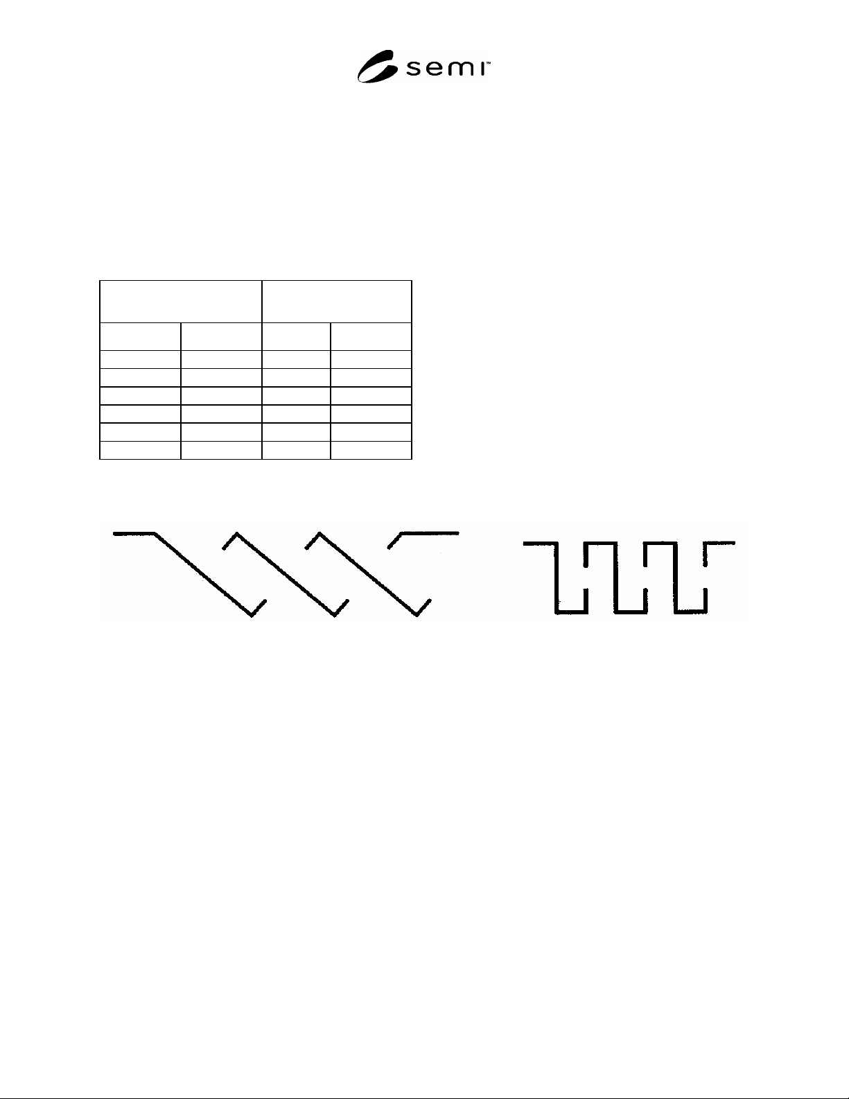
A1-2 Top Openings in Electrical Enclosures — The
top openings in electrical enclosures should meet one of
the following:
not exceed 5 mm in any dimension, or
not exceed 1 mm in width regardless of length, or
be so constructed that direct, vertical entry of a
falling object is prevented from reaching
uninsulated live parts within the enclosure by
means of trap or restriction (see Figure A1-1 below
for examples of top cover designs that prevent such
direct entry), or
meet the intent through other equivalent means.
Figure A1-1
SLANTED OPENINGS VERTICAL OPENINGS

SEMI S2-0703a
E
© SEMI 1991, 2004 34
APPENDIX 2
DESIGN PRINCIPLES AND TEST METHODS FOR EVALUATING
EQUIPMENT EXHAUST VENTILATION — Design and Test Method
Supplement Intended for Internal and Third Party Evaluation Use
NOTICE: The material in this appendix is an official part of SEMI S2 and was approved by full letter ballot
procedures on December 15, 1999 by the North American Regional Standards Committee.
A2-1 Introduction
A2-1.1 This appendix provides specific technical
information relating to Section 22. In general, it
provides guidelines for:
ventilation design for semiconductor manufac-
turing equipment, and
test validation criteria.
A2-1.2 This appendix is intended to be used as a
starting point for reference during equipment design.
A2-1.3 This appendix is not intended to limit hazard or
test evaluation methods or control strategies (e.g.
design principles) employed by manufacturers or users.
Many different methods may be employed if they
provide a sufficient level of protection.
A2-1.4 This appendix is not intended to provide
exhaustive methods for determining final ventilation
specifications. Other methods may be used where they
provide at least equivalent sensitivity and accuracy.
A2-1.5 The exhaust velocities, volume flow rates and
pressures listed are derived from a mixture of
successful empirical testing and regulatory
requirements.
A2-1.6 Test validation criteria are generally referenced
from the applicable internationally recognized standard.
It is the user’s responsibility to ensure that the most
current revision of the standard is used.
Table A2-1 Ventilation
Hood Type Recommended Test Methods Typical Design and Test Exhaust
Parameters (See NOTE 1.)
References
Wet Station Primary: vapor visualization, air
sampling
Supplemental: Capture velocity, slot
velocity, tracer gas, air sampling
0.28–0.50 m/s (55–100 fpm) capture
velocity for non-heated
0.36–0.76 m/s (70–150 fpm) capture
velocity for heated
110–125% of the laminar flow
volume flow rate across the top of
the deck
ACGIH Industrial
Ventilation Manual
SEMI F15
Gas Cylinder
Cabinets
Primary: face velocity, tracer gas
Supplemental: vapor visualization
1.0–1.3 m/s (200–250 fpm) face
velocity
ACGIH Industrial
Ventilation Manual
SEMI F15
Equipment Gas
Panel Enclosure
Primary: tracer gas, static pressure
Supplemental: vapor visualization
4–5 air changes per minute
–1.3 to –2.5 mm (–0.05 to –0.1 in.)
H
2
O static pressure
ACGIH Industrial
Ventilation Manual
SEMI F15
Diffusion
Furnace
Scavenger
Primary: face velocity, vapor
visualization
Supplemental: tracer gas, air sampling
0.50–0.76 m/s (100–150) fpm face
velocity
NOTE: Do not use hot wire
anemometer.
ACGIH Industrial
Ventilation Manual
SEMI F15
Chemical
Dispensing
Cabinets
Primary: static pressure
Supplemental: vapor visualization, air
sampling where safe, tracer gas where
emission rates can be accurately
calculated
–1.3 to –2.5 mm (–0.05 to –0.1 in.)
H
2
O static pressure
2–3 air changes per minute
ACGIH Industrial
Ventilation Manual
SEMI F15