semi合集-English.pdf - 第3902页
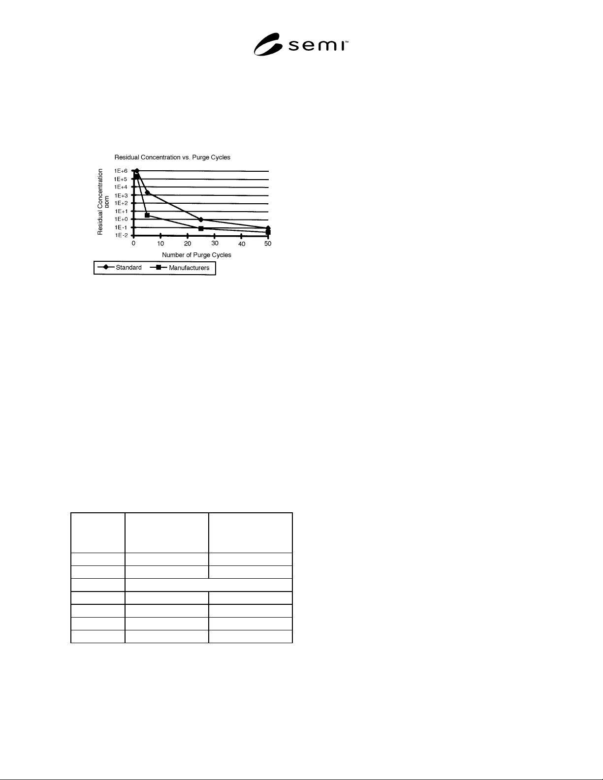
SEMI F29-0997 © SEMI 1997, 1103 5 Figure 3 Data Presentation for Purge Effic acy Interactive Gas 9.4 Purge efficacy determina tion with interactive gas at standard pressure, vacuum , and dwell time. 9.4.1 Connect gas sou…
SEMI F29-0997 © SEMI 1997, 1103 4
9.2.3 Using purified nitrogen as the purge gas,
complete one purge cycle with the purge gas pressure at
522 kPa (g) [80 psi (g)], vacuum at -75 kPa (g) [-22"
Hg (g)], and dwell times for pressurization and vacuum
evacuation at 5 and 15 seconds, respectively.
Figure 2
Data Presentation for Purge
Efficacy — Non-Interactive Gas
9.2.4 Flow purified nitrogen using a pigtail bleed at 1
slpm or at the oxygen analyzer manufacturer’s
recommended flow rate, whichever is higher, into the
oxygen analyzer for 10 minutes or until below the
detection limit of the oxygen analyzer.
9.2.5 Record the pressure and vacuum measured with
the transducer and the peak oxygen concentration as in
Table 1. It is highly recommended that, in addition to
the peak oxygen concentration, the oxygen
concentration readings also be recorded at regular
intervals during the measurement, so that a graph of the
oxygen concentration level in the pigtail bleed gas
versus time can be drawn if necessary.
Table 1 Data Collection Form
Manufacturer’s
Recommended Purge
Parameters
SEMI Standard Purge
Parameters
Pressure kPa (g)
Vacuum kPa (g)
Cycles Peak Residual Oxygen
1
5
25
50
9.2.6 Repeat Sections 9.2.2–9.2.5 process for 2, 5, 25,
and 50 cycles. Additional tests using other purge cycle
numbers are encouraged and may provide a more
complete characterization of the purge performance of
the test piece.
9.2.7 Plot the peak residual oxygen concentration
versus number of cycles as in Figure 2 for standard
pressures, vacuum, and dwell time.
9.3 Purge efficacy determination with interactive gas at
manufacturer’s pressure, vacuum, and dwell times.
9.3.1 Connect gas source equipment as in Figure 1.
9.3.2 To challenge the gas panel with a known
contaminant gas, flow wet (2 ppm) N
2
at 2 slpm and
138 kPa (g) [20 psi (g)] for 30 minutes or until the
process outlet concentration reaches the inlet
concentration, whichever is less.
9.3.3 Using purified nitrogen as the purge gas,
complete one purge cycle at manufacturer’s
recommended pressure, vacuum, and dwell times.
9.3.4 Flow purified nitrogen using a pigtail bleed at 1
slpm or at the moisture analyzer manufacturer’s
recommended flow rate, whichever is higher, into the
moisture analyzer for 30 minutes or until below the
detection limit of the moisture analyzer.
9.3.5 Record the pressure and vacuum measured with
the pressure transducer and peak residual moisture
concentration in Table 2. It is highly recommended that,
in addition to the peak moisture concentration, the
moisture concentration readings also be recorded at
regular intervals during the measurement, so that a
graph of the moisture concentration level in the pigtail
bleed gas versus time can be drawn if necessary.
9.3.6 Repeat Sections 9.3.2–9.3.5 process for 2, 3, 4, 5,
10, 25, and 50 cycles. Additional tests using other purge
cycle numbers are encouraged and may provide a more
complete characterization of the purge performance of
the test piece.
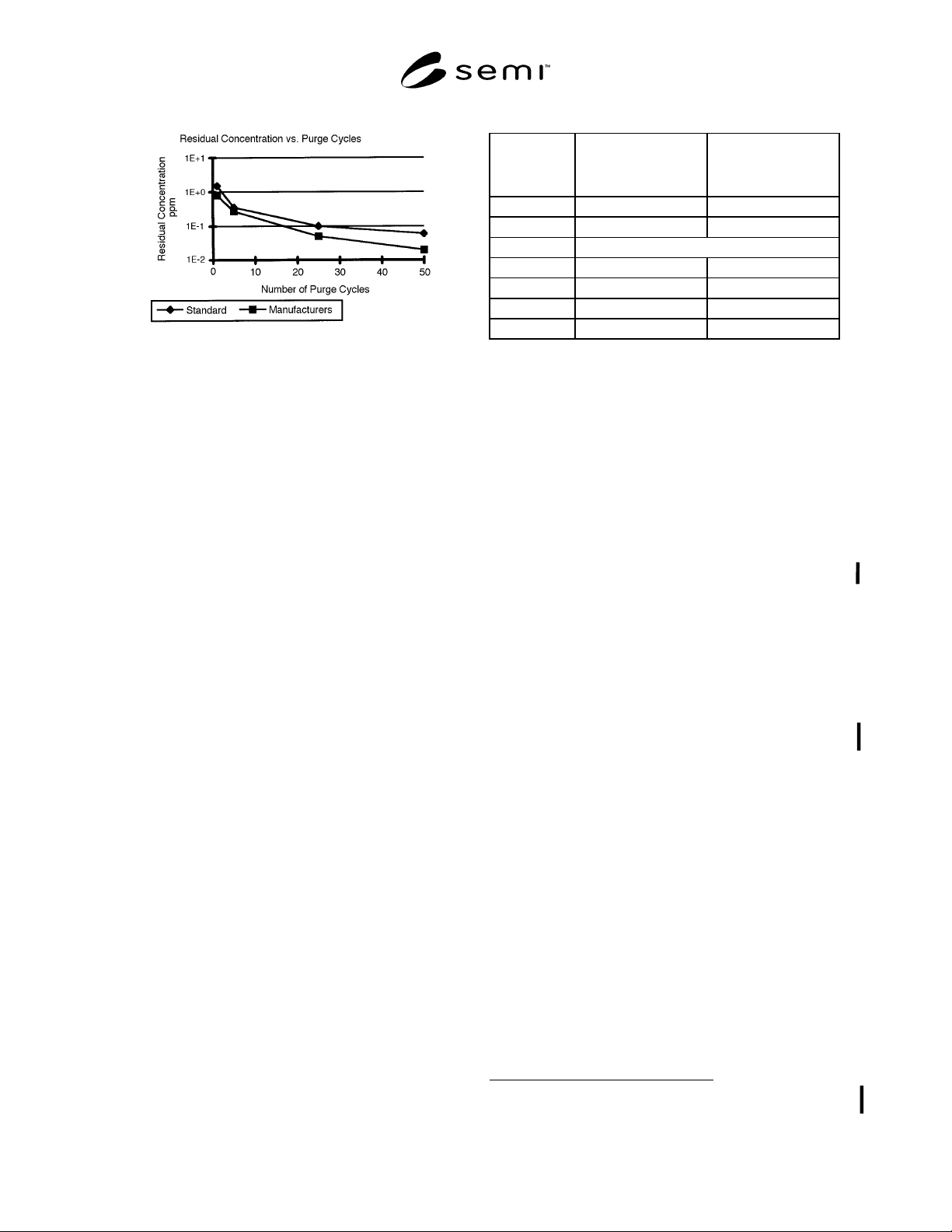
9.3.7 Plot the peak residual moisture concentration
versus number of cycles as in Figure 3 for
manufacturer’s pressure, vacuum, and dwell time.
SEMI F29-0997 © SEMI 1997, 1103 5
Figure 3
Data Presentation for Purge Efficacy
Interactive Gas
9.4 Purge efficacy determination with interactive gas at
standard pressure, vacuum, and dwell time.
9.4.1 Connect gas source equipment as in Figure 1.
9.4.2 To challenge the gas panel with a known
contaminant gas, flow wet (2 ppm) N
2
at 2 slpm and
138 kPa (g) [20 psi (g)] for 30 minutes or until the
process outlet concentration reaches the inlet
concentration, whichever is less.
9.4.3 Using purified nitrogen as the purge gas,
complete one purge cycle with the purge gas pressure at
522 kPa (g) [80 psi (g)], vacuum at -75 kPa (g) [-22"
Hg (g)], and dwell times for pressurization and vacuum
evacuation at 5 and 15 seconds, respectively.
9.4.4 Flow purified nitrogen using a pigtail bleed at 1
slpm or at the moisture analyzer manufacturer’s
recommended flow rate, whichever is higher, into the
moisture analyzer for 30 minutes or until below the
detection limit of the moisture analyzer.
9.4.5 Record the pressure and vacuum measured with
the pressure transducer and peak residual moisture
concentration in Table 2. It is highly recommended that,
in addition to the peak moisture concentration, the
moisture concentration readings also be recorded at
regular intervals during the measurement, so that a
graph of the moisture concentration level in the pigtail
bleed gas versus time can be drawn if necessary.
9.4.6 Repeat Sections 9.4.2–9.4.5 process for 2, 3, 4, 5,
10, 25, and 50 cycles. Additional tests using other purge
cycle numbers are encouraged and may provide a more
complete characterization of the purge performance of
the test piece.
9.4.7 Plot the peak residual moisture concentration
versus number of cycles as in Figure 4 for standard
pressure, vacuum, and dwell time.
Table 2 Data Collection Form
Manufacturer’s
Recommended Purge
Parameters
SEMI Standard Purge
Parameters
Pressure kPa (g)
Vacuum kPa (g)
Cycles Peak Residual Moisture
1
5
25
50
10 Certification
10.1 When specified in the purchase order or contract,
the manufacturer’s or supplier’s certification shall be
furnished to the purchaser stating that the articles
furnished have been tested in accordance with this
specification and the requirements have been met.
When specified in the purchase order or contract, a
report of the test results shall be furnished.
11 Related Documents
11.1 SEMI Standard
SEMI F13 — Guide for Gas Source Control Equipment
11.2 Compressed Gas Association Document
1
CGA Pamphlet P1 — Safe Handling of Compressed
Gases
NOTICE: SEMI makes no warranties or
representations as to the suitability of the standards set
forth herein for any particular application. The
determination of the suitability of the standard is solely
the responsibility of the user. Users are cautioned to
refer to manufacturer’s instructions, product labels,
product data sheets, and other relevant literature
respecting any materials mentioned herein. These
standards are subject to change without notice.
The user’s attention is called to the possibility that
compliance with this standard may require use of
copyrighted material or of an invention covered by
patent rights. By publication of this standard, SEMI
takes no position respecting the validity of any patent
rights or copyrights asserted in connection with any
item mentioned in this standard. Users of this standard
are expressly advised that determination of any such
patent rights or copyrights, and the risk of infringement
of such rights, are entirely their own responsibility.
1 Compressed Gas Association, Inc., 1725 Jefferson Davis Highway,
Suite 1004, Arlington, VA 22202
Copyright by SEMI® (Semiconductor Equipment and Materials
International), 3081 Zanker Road, San Jose, CA 95134. Reproduction o
f
the contents in whole or in part is forbidden without express written
consent of SEMI.

SEMI F30-0298 © SEMI 19981
SEMI F30-0298
START-UP AND VERIFICATION OF PURIFIER PERFORMANCE
TESTING FOR TRACE GAS IMPURITIES AND PARTICLES AT AN
INSTALLATION SITE
1 Purpose
1.1 The purpose of this procedure is to verify the
performance of purifiers by employing analytical
instrumentation to measure gas impurities and particles
to customer specifications. If specific inlet challenge(s)
and/or inlet measurements are required, it should be
discussed beforehand with the customer. Inlet
impurities must be measured by part-per-million (PPM)
or part-per-billion (PPB) analytical equipment. This
procedure applies only to large scale bulk purifiers
rated at greater than 50 liters-per-minute (LPM)
flowrate.
2 Scope
2.1 Verify performance of large scale purifiers in
nitrogen, argon, helium, oxygen, and hydrogen service.
Verification tests are done at PPB or sub-PPB levels of
gaseous impurities and sub-micron sizes of particles
measured downstream of any installed filter modules.
Tests are done at maximum achievable flow of purifier,
and/or customer’s specified percentages of maximum
flow.
3 Limitations
3.1 PPB and sub-PPB gaseous impurity levels are
achievable using atmospheric presssure ionization mass
spectrometry (APIMS), which is the preferred method
of choice, and the reduction gas detector (RGD)-gas
chromatograph. APIMS is currently not available for
oxygen service. A partial list of non-APIMS measuring
equipment for use in oxygen service is in Appendix 1
for commonly measured impurities.
4 Referenced Documents
4.1 Approved procedures for operation of analytical
equipment.
4.2 Approved gas sampling and purifier procedures.
5 Terminology
None.
6 Summary of Method
6.1 The purifier is started, and the operation is
checked. Each purifier bed is regenerated, and
analytical tests are done. The analytical results
determine if the purified gas meets the customer
specifications.
7 Interferences
7.1 The following sources might contribute to
misleading or high analytical results. Some identified
sources are unpurged, dead-ended piping or isolation
valves, leaks in gas distribution system, insufficient
purge flow, and insufficient system clean-up time.
8 Apparatus
8.1 Face seal fitting(s) with metal gaskets and stainless
steel tubing for sampling.
8.2 Dynamic dilution system for diluting calibration
standards to PPB and sub-PPB levels for calibration of
analytical equipment.
8.3 APIMS — The sample gas, nitrogen, is introduced
into an APIMS where a small amount of it is ionized.
By collision with ionized nitrogen, impurity molecules
are ionized with high efficiency. The mass analyzer,
which can be a quadrupole, time-of-flight (TOF), or
even a magnetic sector, separates and focusses the ions
by their mass-to-charge ratio. An electron multiplier
detects and counts each ion fragment and amount.
8.4 Reduction Gas Detector-Gas Chromatograph
(RGD-GC) — The reduction gas detector is a heated
mercuric oxide bed that reacts with reducing gases,
such as hydrogen and carbon monoxide. The mercury
evolved is detected and displayed as a peak. The GC
employs a heated molecular sieve column to separate
the H
2
and CO.
8.5 Ultratrace Analytical Instrumentation Required
other than APIMS — Ultratrace instrumentation is
defined as having sufficient sensitivity to measure all
impurities of interest at the specified level of the
customer at the PPB or sub-PPB.
8.6 Particle counter.
8.7 Data collection and reduction system.
9 Reagents and Materials
9.1 Certified calibration standards.