semi合集-English.pdf - 第7703页
SEMI T9-0200 © SEMI 1998, 2004 4 6.2.2.3 The condensed message code shall contain 12 to 16 characters. The first 12 characters shall be contained in sub- fields 1 through 3, as listed i n Table 3. The number of message c…
3 SEMI T9-0200 © SEMI 1998, 2004
6 Requirements
6.1 Shape and Size of the Data Matrix Code Symbol
6.1.1 Data Matrix Code Symbol Dimensions
6.1.1.1 Each rectangular matrix code symbol shall be composed of an array of 12 to 16 rows and 26 to 48 columns
as defined in AIM International Symbology Specification - Data Matrix.
6.1.1.2 Each square matrix code symbol shall be composed of an array 16 rows and 16 columns.
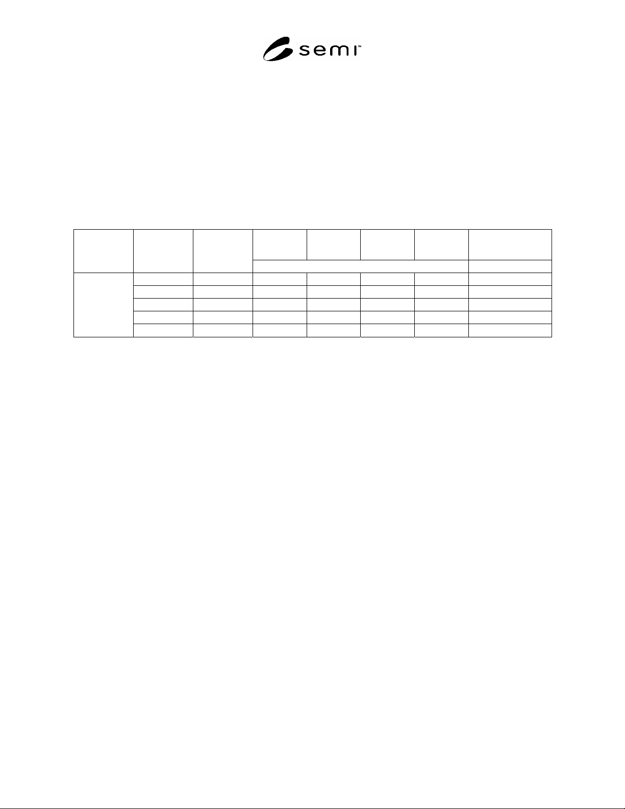
6.1.1.3 Table 1 defines the field dimensions and maximum number of message characters for each of the five
available combinations of rows and columns.
Table 1 2-D Data Matrix Code Symbol Dimensions
C1 R1 C2 R2 # of Message
Characters, Maximum
Cell Spacing
(µm)
# of Cells in
Row
# of Cells in
Column
(mm)
12 26 1.10 2.50 1.20 2.60 22
12 36 1.10 3.50 1.20 3.60 31
16 36 1.50 3.50 1.60 3.60 46
16 48 1.50 4.50 1.60 4.80 72
100
16 16 1.50 1.50 1.60 1.60 16
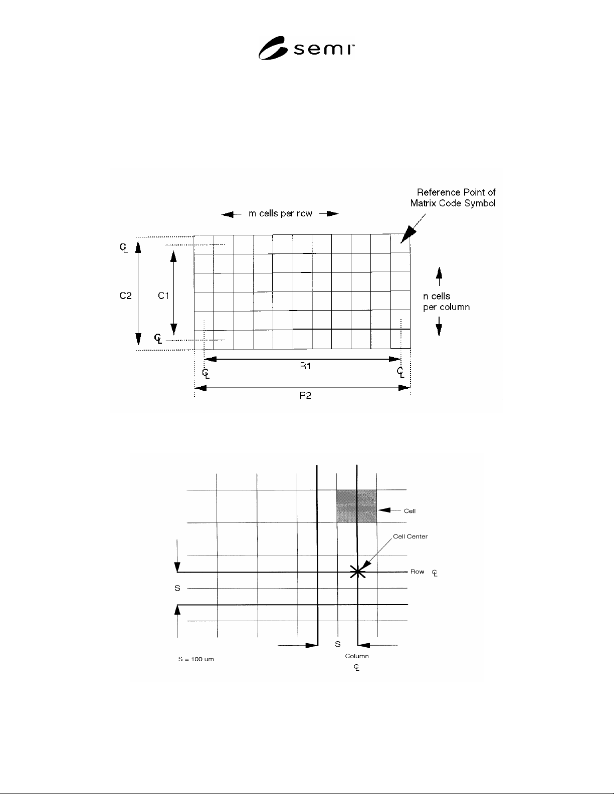
6.1.1.4 Cell spacing shall be 100 µm, center to center.
6.1.2 Dot Size — The nominal shape of the dot produced in the matrix may be circular or square. Its diameter or
edge length shall be 100 ± 10 µm.
1.1.1Border Rows and Columns (see Figure 3)
6.1.2.1 One border row and one border column shall contain a dot in each cell. These are identified as the primary
border row and the primary border column. These are used by the code reader to determine the orientation of the
matrix.
6.1.2.2 The opposing (secondary) border row and column shall contain dots in alternating cells.
6.1.2.3 For these rectangular and square matrix code symbols, the reference point of the symbol shall be the
physical centerpoint of the cell common to the primary border row and the primary border column.
6.1.3 The maximum allowable dot misalignment within a cell is 20 µm. This ensures that a minimum size dot
covers a cell central area of radius 25 µm.
6.2 Content of the Data Matrix Code Symbol
6.2.1 Each matrix code symbol shall contain between 12 and 72 message characters, together with the error
checking and correcting (ECC) 200 code characters, encoded in accordance with AIM International Symbology
Specification - Data Matrix.
6.2.2 The message characters may include any of those designated as “mostly upper case” in Table 5 and Annex K
of AIM International Symbology Specification - Data Matrix. The message characters are contained in a single field
that contains multiple sub-fields (see Table 2). In the absence of a character at any assigned location, a dash (‘-’)
shall be used.
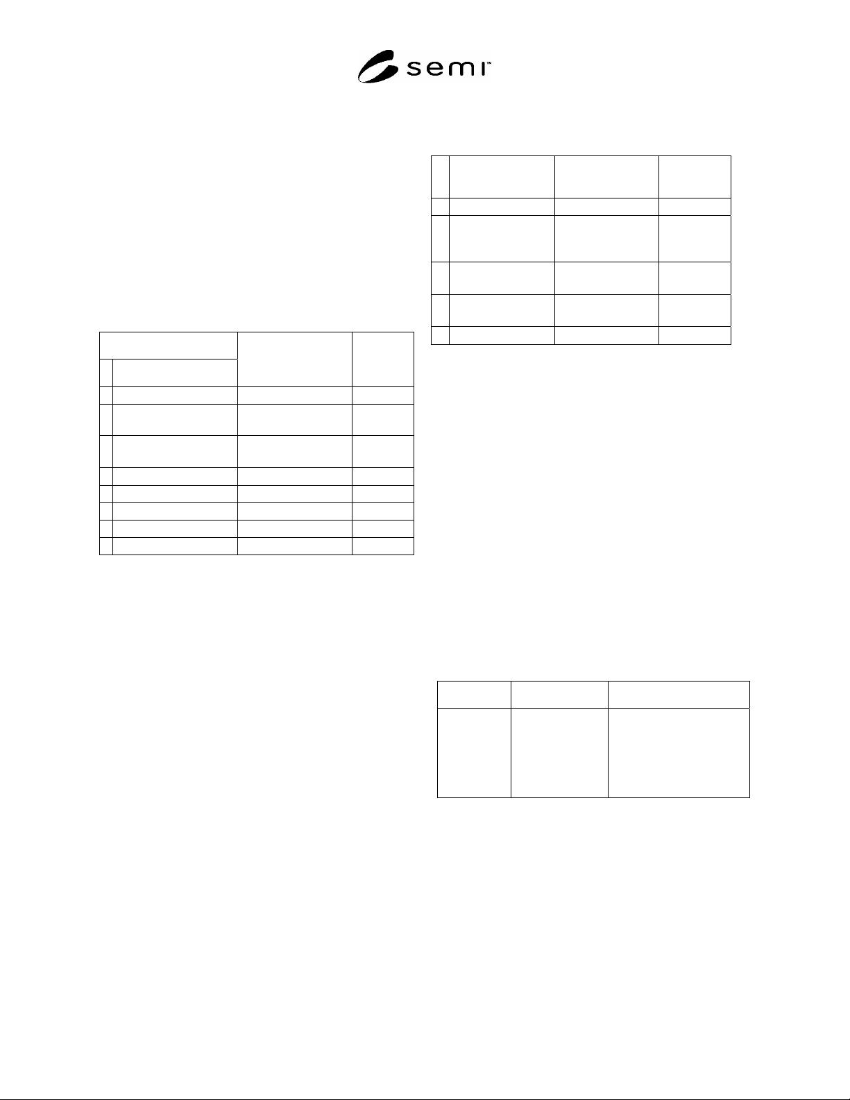
6.2.2.1 The standard message code shall contain 22 or more characters. The first 22 characters shall be contained in
sub-fields 1 through 6 whose content is listed in Table 2. The number of message characters in each of these sub-
fields is fixed. Other sub-fields may be added to the message subject to Section 6.2.2.2. To save space or for other
reasons, a condensed message code may be used as an alternative. Refer to Section 6.2.2.3.
6.2.2.2 Characters 23up, if present, shall contain information as agreed upon between supplier and user. This may
require field identifiers and field concatenators (see ANSI MH10.8.2).
SEMI T9-0200 © SEMI 1998, 2004 4
6.2.2.3 The condensed message code shall contain 12
to 16 characters. The first 12 characters shall be
contained in sub-fields 1 through 3, as listed in Table 3.
The number of message characters in each of these sub-
fields is fixed. Content of sub-field(s) for characters 13
through 16, if present, are to be agreed upon between
supplier and user.
6.2.3 Sub-fields 2 and 3 in Table 2 and Table 3 are
intended to provide a unique identification number for
each strip from a given supplier.
Table 2 Sub-Field Message Characters in
Rectangular Arrays for Use on Lead-Frame Strips
(Standard Message Code)
Sub-Field Content
# Symbol Content
Character Symbols Number of
Characters
1 Field Identifier IT
#1
2
2 Traceability Number:
Coil S/N
vendor assigned
#2
3
3 Traceability Number:
Strip ID
vendor assigned
#2
7
4 Concatenation Symbol + 1
5 Field Identifier 3V
#1
2
6 Supplier ID UCC/EAN coding 7
7 Optional Information Vendor-user agreed 0 to 50
Total 22 to 72
#1: These field identifiers are described in ANSI-FACT-1.
#2: Lead-frame strip suppliers.
Table 3 Sub-Field Message Characters in 16 x 16
Arrays for Use on Lead-Frame Strips (Condensed
Message Code)
# Sub-Field
Content
Character
Symbol
Number of
Characters
1 Field Identifier IT
#1
2
2 Traceability
Number: Coil
S/N
Vendor-
assigned
#2
3
3 Traceability
Number: Strip ID
Vendor-
assigned
#2
7
4 Optional
Information
Vendor-user
agreed
0 to 4
Total Characters 12 to 16
#1: These field identifiers are described in ANSI-FACT-1.
#2: Lead-frame strip suppliers.
6.3 Location of the Data Matrix Code Symbol
6.3.1 With the strip positioned front surface up and
with the strip orientation corner away from the operator
and to the operator’s right, the reference point of the
data matrix code symbol shall be placed adjacent to the
leading edge of the strip, and toward the strip
orientation corner as specified in Table 4 and Figure 5.
6.3.2 The primary row of the symbol shall be parallel
to the adjacent edge of the substrate ± 10.0. The
primary column of the symbol shall be nominally
perpendicular to the same edge. The reference point of
the symbol shall be located 0.3 mm minimum, from the
adjacent strip rail, 2.0 mm minimum, from the adjacent
strip end and toward the strip orientation corner.
Table 4 Location of 2-D Matrix Code Symbol Strip
Front Surface Up, Strip Orientation Corner Away
from the Operator and Toward the Operator's Right
Type of Array Reference Point Location of Reference Point
Rectangular Common cell of
primary border
row and column.
A ± 0.1 mm from the
nominal edge of the rail, B
± 0.5 mm from the adjacent
strip end and toward the
strip orientation corner (see
Section 6.3.4).
5 SEMI T9-0200 © SEMI 1998, 2004
6.3.3 For the default location for the symbol, A = 0.4 mm and B = 2.5 mm.This location may not be acceptable for
all lead strips. The mark may be placed in other locations provided that the following condition is maintained:
6.3.3.1 A zone 0.3 ± 0.1 mm wide and clear of marks and other surface features is maintained around the entire data
matrix code (sometimes called “quiet zone”).
6.3.4 Refer to Figure 6 for examples of acceptable data matrix code locations on several lead-frame designs.
Figure 1
Data Matrix Field Dimensions
Figure 2
Data Matrix Cell Dimensions