semi合集-English.pdf - 第3937页
8 Shut-off Valv es 8.1 Shut -off valves should co nform to the interface desi gn recommendations a ppearing in Figure 2 and Table 2. Figure 2 Shut-off Val ve Interface Design SEMI F36-0299 © SEMI 1999, 2004 4
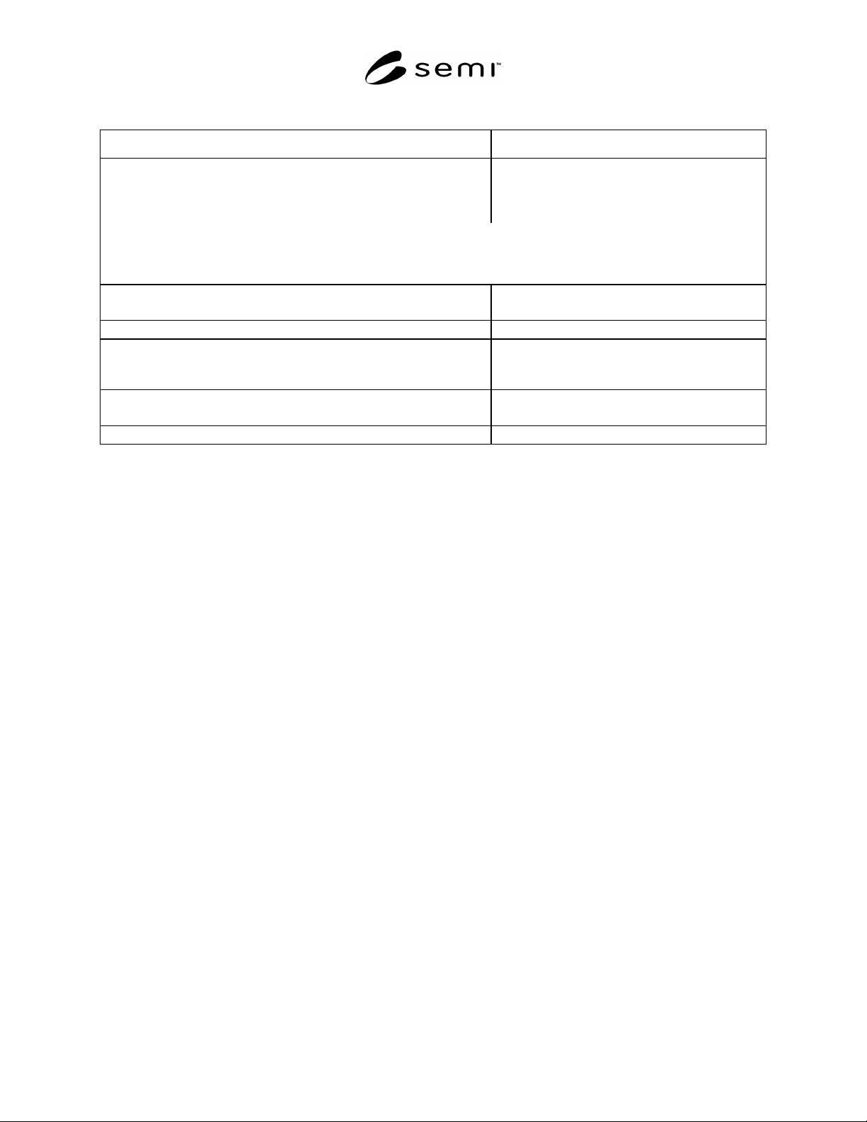
Table 1 Filter and Purifier Interface Recommendations
Filter and Purifier
End-to-End Lengths:
1/4-inch Integral/fixed male face seal
1/4-inch Swivel face seal (male or female)
1/4-inch Tube weld
84 mm (3.31 in.)
-
-
NOTE 1: The tolerance on length for machined components is ± 0.15 mm (0.006 in.) from the component centerline to each
end.
NOTE 2: The tolerance on length for welded components is ± 0.5 mm (0.020 in.) from the component centerline to each end.
Overall Component Envelope:
Maximum Diameter
38 mm (1.5 in.)
Base to Centerline of Flow Path:
-
Mounting provisions:
Threaded holes
Pattern
None required
-
Fittings:
Process
1/4-inch
Control:
None required
SEMI F36-0299 © SEMI 1999, 2004 3

8 Shut-off Valves
8.1 Shut-off valves should conform to the interface design recommendations appearing in Figure 2 and Table 2.
Figure 2
Shut-off Valve Interface Design
SEMI F36-0299 © SEMI 1999, 2004 4
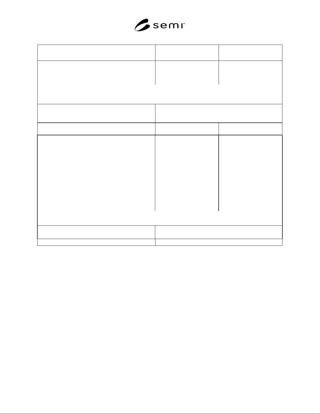
Table 2 Shut-off Valve Interface Recommendations
Option 1
Shut-off Valves
Option 2
Shut-off Valves
End-to-End Lengths:
1/4 inch Integral/fixed male face seal
1/4 inch Swivel face seal (male or female)
1/4 inch Tube weld
58 mm (2.28 in.)
70.5 mm (2.78 in.)
44.5 mm (1.75 in.)
52 mm (2.05 in.)
66 mm (2.60 in.)
-
NOTE 1: The minimum length for each tube weld stub should be 6.5 mm (0.26 in.). The tolerance on length for machined
components is ± 0.15 mm (0.006 in.) from the component centerline to each end. The tolerance on length for welded
components is ± 0.50 mm (0.020 in.) from the component centerline to each end.
Overall Component Envelope:
Maximum height
Maximum width (Excluding lever and toggle handles)
180 mm (7.1 in.)
38 mm (1.5 in.)
Base to Centerline of Flow Path:
11 mm (0.44 in.)
± 0.3 mm (0.012 in.)
10 mm (0.39 in.)
± 0.3 mm (0.012 in.)
Mounting Provisions:
Threaded holes
Pattern
M5 0.8 6H; 6 mm (0.24
in.) perfect thread depth
25.4 mm (1.00 in.) bolt circle
centered on bottom of base
with two threaded holes 180°
apart and 45° off of the vertical
or horizontal axis.
One hole in each of the upper
left and lower right quadrants
when looking at the bottom of
the component.
M5 0.8 6H; 5mm (0.20 in.)
perfect thread depth
17 mm (0.67 in.) bolt circle
centered on bottom of base
with two threaded holes 180°
apart and 45° off of the vertical
or horizontal axis.
One hole in each of the upper
left and lower right quadrants
when looking at the bottom of
the component.
NOTE 2: The M5 0.8 threaded mounting holes will accept 1032 screws, but 1032 threaded holes will not accept M5 0.8
screws.
Fittings:
Process
1/4-inch
Control:
Manual and Pneumatic
SEMI F36-0299 © SEMI 1999, 2004 5