semi合集-English.pdf - 第1899页
SEMI E54.1-1000 © SEMI 1996, 2000 5 6.4.2.1 Se rvice Message Definition — T he re is a table showing the param eter detail for each service in which parameters are ex plicitl y specified. The colum n headings for the s e…
SEMI E54.1-1000 © SEMI 1996, 2000 4
5.2.18 Signed Integer (INT) — An integer, 2 bytes
long, in the range -32768 to 32767.
5.2.19 text string — A string of one byte characters.
5.2.20 Unsigned Double Integer (UDINT) — An un-
signed integer, four bytes long, in the range 0 to 2
32
-1.
5.2.21 Unsigned Integer (UINT) — An integer, 2
bytes long, in the range 0 to 65535.
5.2.22 Unsigned Long Integer (ULINT) — An un-
signed integer, eight bytes long, in the range 0 to 2
64
-1.
5.2.23 Unsigned Short Integer (USINT) — An integer,
1 byte long, in the range 0 to 255.
6 Conventions
6.1 Harel State Model — This document uses the
Harel State Chart notation to describe the dynamic
behavior of the objects defined. An overview of this
notation is presented in an appendix of SEMI E30. The
formal definition of this notation is presented in Science
of Computer Programming 8, “Statecharts: A Visual
Formalism for Complex Systems,” by D. Harel, 1987.
Transition tables (referred to in this document as “state
transition matrices”) are provided in conjunction with
the state diagrams to explicitly describe the nature of
each state transition. Each transition table contains
columns for Transition #, Current State, Trigger, New
State, Action(s). The “trigger” (column 3) for the
transition occurs while in the “current” state. The
“actions” (column 5) include a combination of: 1)
actions taken upon exit of the current state, 2) actions
taken upon entry of the new state, and 3) actions taken
which are most closely associated with the transition.
No differentiation is made.
6.2 OMT Object Information Model — The object
models are presented using the Object Modeling
Technique developed by Rumbaugh, James, et al, in
“Object-Oriented Modeling and Design,” Prentice Hall,
Englewood Cliffs, NJ, ©1991. Overviews of this
notation are provided in an appendix of SEMI E39.
6.3 Object Attribute Representation — The object
information models for standardized objects will be
supported by an attribute definition table with the
following column headings:
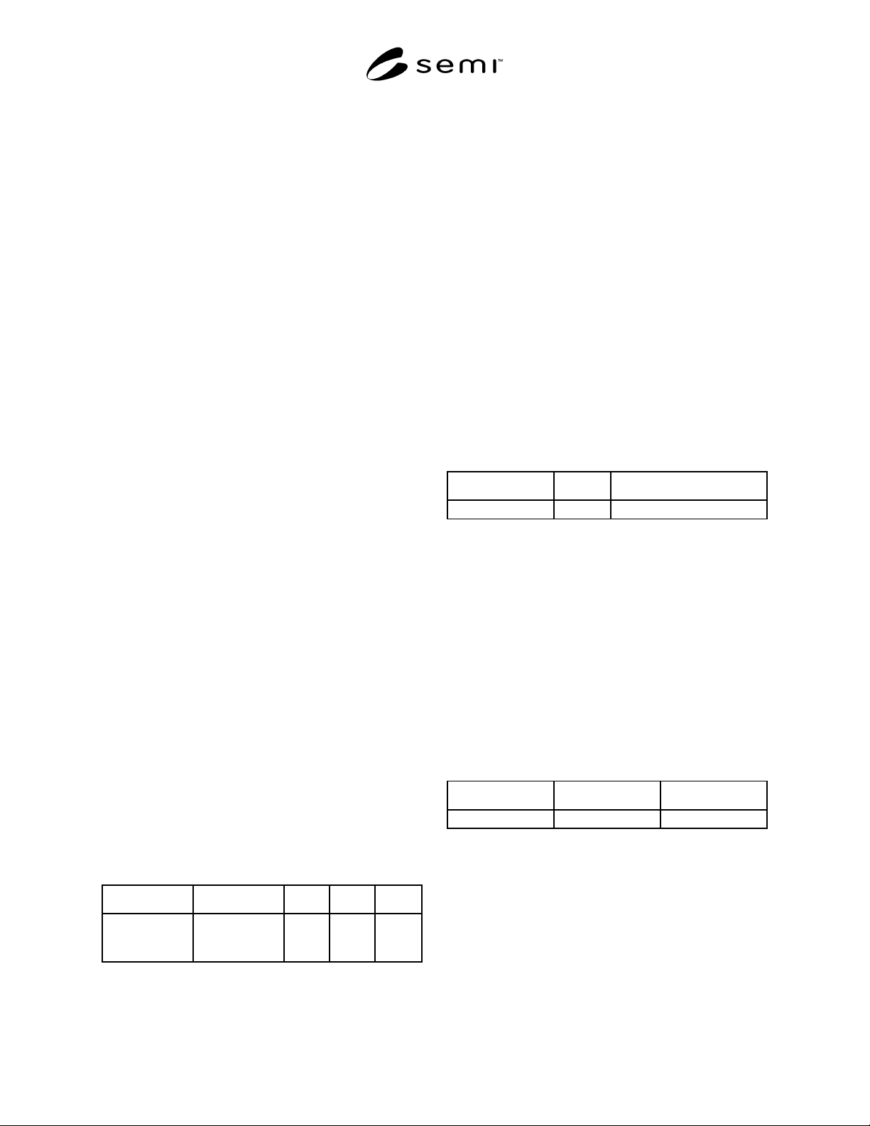
Attribute Definition Access Rqmt Form
The formal text
name of the
attribute.
Description of
the information
contained.
RO or
RW
Y or N (see
below)
The access column uses RO (Read Only) or RW (Read
and Write) to indicate the access that users of Object
Services have to the attribute. Note that, in this
document, the access column is used only to indicate
user access via the network; no indication is made as to
local access as this level of specification is considered
to be implementation-specific. Thus, in the context of
this document, a RW attribute is a network-settable
attribute (i.e., an attribute whose value can be altered
from the network), while a RO attribute is a non-
network-settable attribute.
A ‘Y’ or ‘N’ in the requirement (Rqmt) column
indicates if this attribute must be supported in order to
meet fundamental compliance for the service.
The Form column is used to indicate the format of the
attribute.
6.4 Service Message Representation
6.4.1 Service Resource Definition — The service
resource definition table defines the specific set of
messages for a given service group, as shown in the
following table:
Service Type Description
Message name N or R The intent of the service.
Type can be either Notification (N) or Request (R).
Notification messages are initiated by the service
provider. No response is expected. Request messages
are initiated by the service user. Request messages ask
for data or for an operation to be performed. Request
messages expect a specific response (no presumption
on the message content).
6.4.2 Service Parameter Dictionary — Each parameter
should relate to either attributes from the object model
or events of the dynamic model (Harel State Chart). All
parameters to the services are listed in a single table or
dictionary. The column headings for this parameter
dictionary are as follows:
Parameter Form Description
Parameter X Data type A parameter
A row is provided in the table for each parameter of the
service. The first column contains the name of the
parameter. This is followed by columns describing the
form and the contents of the parameter.
The form column is used to indicate the type of data
contained in the parameter and the possible values it
may take on.
The description column describes the meaning of the
parameter and interrelationships with other parameters.
SEMI E54.1-1000 © SEMI 1996, 20005
6.4.2.1 Service Message Definition — There is a table
showing the parameter detail for each service in which
parameters are explicitly specified. The column
headings for the service detail are as follows:
Parameter Req/Ind Rsp/Cnf Description
Parameter X (see below) (see below) A description of the
service.
The columns labeled Req/Ind and Rsp/Cnf link the
parameters to the direction of the message. The mes-
sage sent by the initiator is called the “Request” (Req).
The receiver terms the message the “Indication” (Ind).
The receiver may then send a “Response” (Rsp), which
the original sender terms the “Confirmation” (Cnf).
The request (Req/Ind) and response (Rsp/Cnf) entries
can take on the following values:
“M” Mandatory parameter — Must be given a
valid value.
“C” Conditional parameter — May be defined in
some circumstances and undefined in others.
Whether a value is given may be completely optional
or may depend on the value of another parameter.
“U” User-defined parameter
“-” The parameter is not used.
“=” The entries M and C in the response can be
modified with (=) to indicate that the value in the
response must match the request.
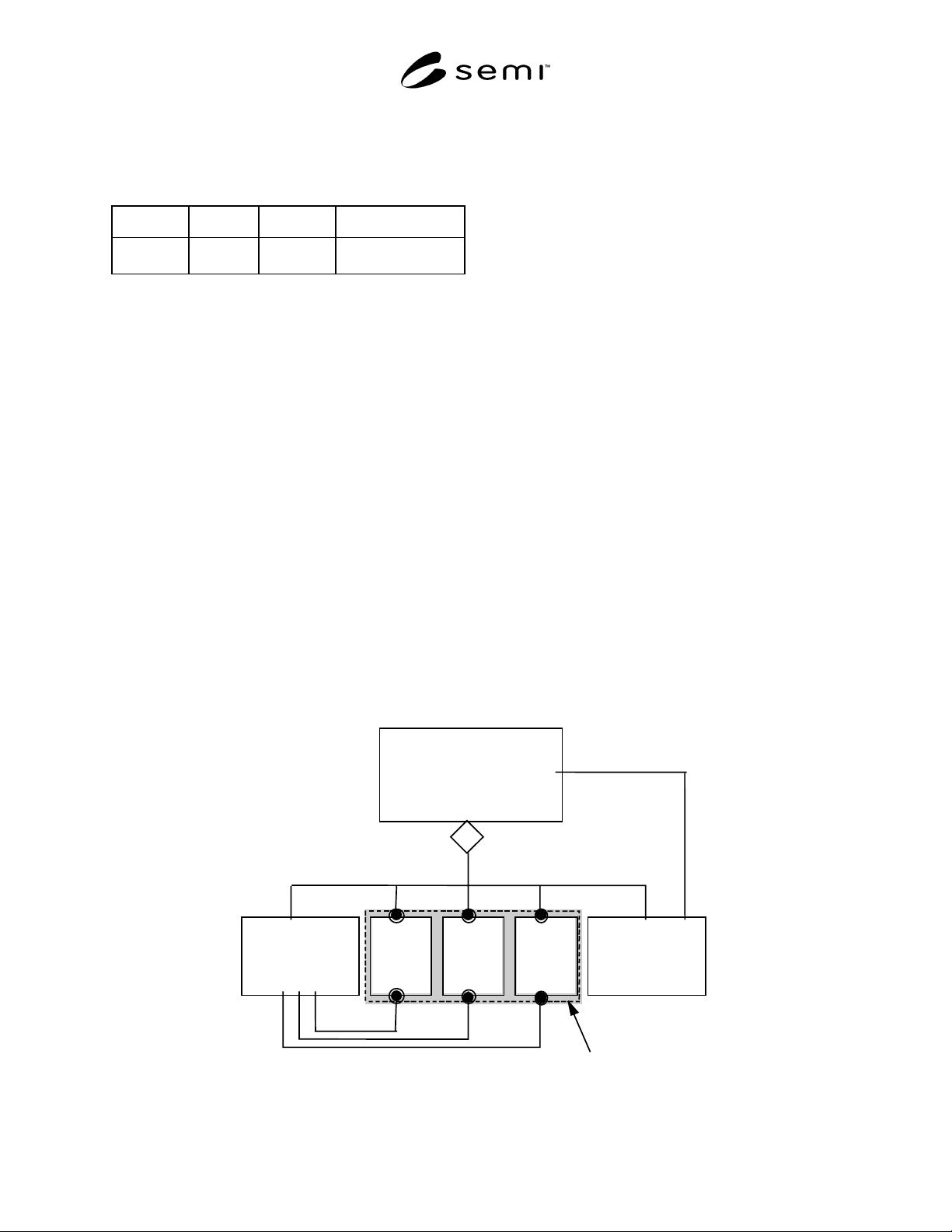
7 Device High Level Structu re
The high level object view of a device aggregation is
shown in Figure 3. A device is depicted as consisting of
a sensor/actuator/controller (SAC) object, a device
manager (DM) object, and at least one active element
object (i.e., sensor or actuator or controller object).
Each of these objects by definition has attributes,
services, and behavior. Note that the “Device” object is
depicted in Figure 3 only for purposes of illustrating a
high level view of the device and its component
objects; in the context of this document, the “Device”
object is not addressable, does not have addressable
attributes or accessible services, and has no behavior
defined.
This document defines in detail only the DM object.
The SAC, Sensor, Actuator, and Controller objects are
defined here only in terms of characteristics common to
all devices. A complete definition of a SAC object in-
cludes an appropriate sensor/actuator network specific
device model. This companion model could also com-
plete the definition of sensor, actuator, and controller
objects as appropriate to specify a device model.
7.1 General Requirements — Objects are defined in
terms of their object name and instance identifier.
Identifiers for all objects described in this document are
summarized in Table 2. Note that these identifiers may
be used for remote interrogation of an object instance
via the sensor/actuator network (see appropriate
sensor/actuator communications specification). Also
note that, in Table 2, many of the objects specified in
this document have exactly one instantiation per device.
De vice M an a
g
er
Ob
j
ect
(
DM
)
De v ice
Sens or
/
Actuator
/
Controller Ob
j
ect
(
SAC
)
Sensor
Ob
j
ect
(
s
)
A
ctuator
Ob
j
ect
(
s
)
Controller
Ob
j
ect
(
s
)
Coord
i
na
t
es
I
s
M
anaged By
m+n+p•1
mnp
mnp
(
A
g
g
re
g
ation
)
Act iv e Element
Figure 3
High Level Object View of a Device
SEMI E54.1-1000 © SEMI 1996, 2000 6
Table 2 Device Objects and Identifiers
Object Name Object Identifier (tag) Support Required
in a Device
Comment
Sensor/Actuator/Controller SacI0* Yes Only one instance per device allowed.
Sensor SenIn** No Zero or more instances per device allowed.***
Actuator ActIn** No Zero or more instances per device allowed.***
Controller CntIn** No Zero or more instances per device allowed.***
Device Manager DmI0* Yes Only one instance per device allowed.
* Only one object instance per device; identifier uses “I0” to specify “instance zero.”
** “In” is used to indicate the instance number of the object; “n” is a non-negative integer.
*** The specification of the number of sensor, actuator, and/or controller object instances allowed per device may be further constrained by the
appropriate sensor/actuator network specification.
The objects described in this document collectively define a device’s capabilities, including how it has been
configured for network interoperability. The information in the attributes of these object instances must be
accessible over the network and stored at the device.
Character strings described in this document have a prescribed maximum length. If the contents of the string are
shorter than the prescribed length, the string must be terminated with the null character: a byte whose value is 00h.
Note that this specification of null termination does not indicate that a sensor/actuator network protocol
implementation communicating a character string over a network must send the null termination; the presentation of
character string data over a network is sensor/actuator network communication protocol-specific.
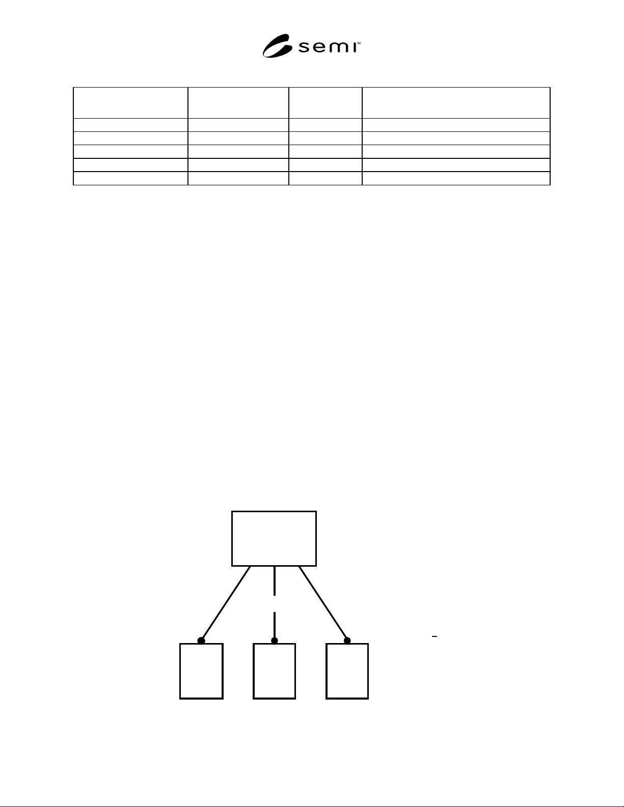
7.2 Sensor/Actuator/Controller (SAC) Object — The SAC object is the device component responsible for
coordinating the interaction of the device with the sensory/actuation/control environment. A view of the SAC object
is shown in Figure 4. The SAC object coordinates operation of one or more sensor, actuator, and/or control object
instances that collectively form the sensory/actuation/control portion of the device, so as to enable desired device
behavior. For example, it could coordinate the operation of the device sensor, actuator, and/or control elements to
enable device level data reporting or actuation, alarming detection and servicing, status reporting, device self-
testing, device shutdown, etc. The number of sensor, actuator, and/or controller object instances allowed per device
may be specified by the appropriate sensor/actuator network specific device model. An operating device shall
contain exactly one instance of a SAC object.
The SAC object has embedded in it other objects that address specific tasks associated with coordinating the
interaction of the device with the sensor/actuation/control environment. These objects are listed in Table 3. Note that
although only one instance of the SAC object is allowed per device, a device can have multiple instances of
embedded objects. These objects are described in Section 7.2.4.
m + n + p > 1
Sensor / Actuator /
Controller Object
(SAC)
S
m
A
n
C
p
Sensor
Object(s)
Actuator
Object(s)
Coordinates
Controller
Object(s)
mn p
Figure 4
Detailed View of the Sensor/Actuator/Controller Object