semi合集-English.pdf - 第3921页
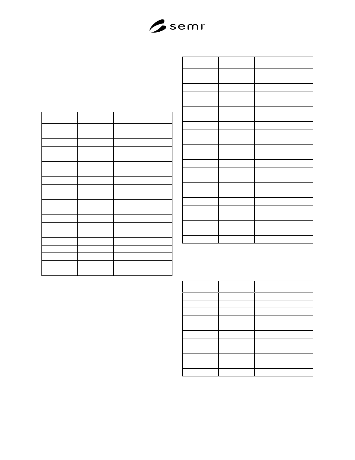
SEMI F33-0998 © SEMI 1998 4 Table 4 Comm on Masses in Heliu m Bulk Gas m/z Ions Source 4H e + Bulk Gas 5H e H + Ana l yte 8H e 2 + Bulk Gas 9H e 2 H + Ana l yte 12 H e 3 + Bulk Gas 12 C + Ana l yte 14 N + Ana l yte 15 CH…
SEMI F33-0998 © SEMI 19983
13.4.1 The validity of the mass selected for each
impurity must be confirmed (i) by demonstrating that
the intensity at the mass increases monotomically with
added concentration of the impurity species of interest
and (ii) that other usually present impurity species do
not make significant contributions to the intensity at
that mass. Tables 1–4 list the typical masses for various
species in argon, nitrogen, hydrogen and helium.
Table 1 Common Masses in Argon Bulk Gas
m/z Ions Source
14 N
+
Analyte
15 CH
3
+
Analyte
16 CH
4
+
Analyte
17 OH
+
Analyte
18 H
2
O
+
Analyte
19 H
3
O
+
Analyte
20 Ne
+
Bulk Gas Impurity
28 CO
+
Analyte
32 O
2
+
Analyte
36 Ar
+
Bulk Gas Isotope
37 (H
2
O)
2
H
+
Analyte
38 Ar
+
Bulk Gas Isotope
40 Ar
+
Bulk Gas
41 ArH
+
Analyte
44 CO
2
+
Analyte
68 ArCO
+
Analyte
68 ArN
2
+
Analyte
76 Ar
2
+
Bulk Gas Isotope
78 Ar
2
+
Bulk Gas Isotope
80 Ar
2
+
Bulk Gas
NOTE: In APIMS, the same ion may be formed even though different
parent molecules are introduced into the ionization region. Thus, it is
necessary to be sure that the chosen m/z represents the ion of interest
and that the ion of interest originates from the molecule of interest.
Table 2 Common Masses in Nitrogen Bulk Gas
m/z Ions Source
12 C
+
Analyte
14 N
+
Bulk Gas
15 CH
3
+
Analyte
16 CH
4
+
Analyte
17 OH
+
Analyte
18 H
2
O
+
Analyte
19 H
3
O
+
Analyte
28 N
2
+
Bulk Gas
28 CO
+
Analyte
29 N
2
H
+
Analyte
29 COH
+
Analyte
29 C
2
H
5
+
Analyte
29 N
2
+
Bulk Gas Isotope
32 O
2
+
Analyte
37 (H
2
O)
2
H
+
Analyte
42 N
3
+
Bulk Gas
43 N
3
H
+
Analyte
44 CO
2
+
Analyte
44 N
2
O
+
Analyte
46 N
2
H
2
O
+
Analyte
55 (H
2
O)
3
H
+
Analyte
56 N
4
+
Bulk Gas
70 N
5
+
Bulk Gas
NOTE: In APIMS, the same ion may be formed even though different
parent molecules are introduced into the ionization region. Thus, it is
necessary to be sure that the chosen m/z represents the ion of interest
and that the ion of interest originates from the molecule of interest.
Table 3 Common Masses in Hydrogen Bulk Gas
m/z Ions Source
2H
2
+
Bulk Gas
17 CH
5
+
Analyte
18 H
2
O
+
Analyte
19 H
3
O
+
Analyte
29 N
2
H
+
Analyte
29 COH
+
Analyte
33 O
2
H
+
Analyte
34 O
2
H
2
+
Analyte
35 O
2
H
3
+
Analyte
37 (H
2
O)
2
H
+
Analyte
45 CO
2
H
+
Analyte
NOTE: In APIMS, the same ion may be formed even though different
parent molecules are introduced into the ionization region. Thus, it is
necessary to be sure that the chosen m/z represents the ion of interest
and that the ion of interest originates from the molecule of interest.

SEMI F33-0998 © SEMI 19984
Table 4 Common Masses in Helium Bulk Gas
m/z Ions Source
4He
+
Bulk Gas
5HeH
+
Analyte
8He
2
+
Bulk Gas
9He
2
H
+
Analyte
12 He
3
+
Bulk Gas
12 C
+
Analyte
14 N
+
Analyte
15 CH
3
+
Analyte
16 He
4
+
Bulk Gas
16 CH
4
+
Analyte
18 H
2
O
+
Analyte
20 Ne
+
Bulk Gas Isotope
22 HeH
2
O
+
Analyte
24 NeHe
+
Bulk Gas Impurity
26 He
2
H
2
O
+
Analyte
28 N
2
+
Analyte
28 CO
+
Analyte
28 He
7
+
Bulk Gas
32 O
2
+
Analyte
40 Ar
+
Bulk Gas Impurity
44 CO
2
+
Analyte
44 ArHe
+
Bulk Gas Impurity
NOTE: In APIMS, the same ion may be formed even though different
parent molecules are introduced into the ionization region. Thus, it is
necessary to be sure that the chosen m/z represents the ion of interest
and that the ion of interest originates from the molecule of interest.
14 Procedure
14.1 Zero gas should be passed through the dilution
system and the APIMS. Based on prior calibrations, the
system should be below 100 ppt, or at least an order of
magnitude lower than the lowest calibration point, for
the impurities to be calibrated.
14.2 Prior to beginning the calibration, record all
relevant parameters, such as discharge voltage, lens
voltages, ionization chamber pressure and/or flow, gas
type, etc.
14.3 The user should use the zero gas only, plus a
minimum of 5 challenge concentrations, with a
minimum of 5 data points, with the blended data points
spanning the range of interest of impurity measurement,
excluding the zero point, while maintaining constant
flow to the APIMS. Allow each challenge concentration
to stabilize for at least 15 minutes, and the signal
variation should be less than 3% before taking data
points at that concentration. Record the relevant ion
intensities as a function of time, for each stabilized
concentration.
14.4 Once the linearity of the calibration has been
established, a single point calibration check is
permitted, as long as the accuracy of the dilution system
is confirmed.
15 Calculations or Interpretation of Results
15.1 Perform a regression analysis for the individual
ion intensities against the impurity concentration. Be
sure to use only ion intensities below the saturation
region of your APIMS ion counting electronics, if using
counting detection. (Ask the manufacturer for the
saturation region of the units counting electronics.) The
R
2
from the fit of all the regression coefficients should
be 0.98 or above. If this is not the case, the calibration
will have to be repeated as described in the previous
section.
16 Reporting Results
16.1 As a minimum, the calibration will include the
following information for each impurity:
y = c
0
+ c
1
* x
(
1)
where,
y is the ion intensity, c
0
is ion intensity
background, c
1
is the linear response factor,
and x is the impurity level.
16.2 As an option, a quadratic regression may be
reported for the calibration, and will include the
following information for each impurity:
y = c
0
+ c
1
* x + c
2
* x
2
(2)
where,
y is the ion intensity, c
0
is ion intensity
background, c
1
is the first order response
factor, c
2
is the second order response factor
and x is the impurity level.
The c
0
/c
1
ratio or negative x - intercept is
useful to define the background concentration
of each particular ion. All regression coefficients
should be reported.
17 Precision and Accuracy
17.1 This method does not explicitly consider the
estimation of the accuracy of the impurity standard in
detail, because such a calculation can be made by
applying procedures described elsewhere. The precision
and accuracy required in validation will vary with the
proposed application and may be left to the discretion

SEMI F33-0998 © SEMI 19985
of the user of the method. If an accuracy statement is
given, then a propagation of error calculation must be
provided to estimate the accuracy of the validation.
NOTICE: These standards do not purport to address
safety issues, if any, associated with their use. It is the
responsibility of the user of these standards to establish
appropriate safety and health practices and determine
the applicability of regulatory limitations prior to use.
SEMI makes no warranties or representations as to the
suitability of the standards set forth herein for any
particular application. The determination of the
suitability of the standard is solely the responsibility of
the user. Users are cautioned to refer to manufacturer’s
instructions, product labels, product data sheets, and
other relevant literature respecting any materials
mentioned herein. These standards are subject to
change without notice.
The user’s attention is called to the possibility that
compliance with this standard may require use of
copyrighted material or of an invention covered by
patent rights. By publication of this standard, SEMI
takes no position respecting the validity of any patent
rights or copyrights asserted in connection with any
item mentioned in this standard. Users of this standard
are expressly advised that determination of any such
patent rights or copyrights, and the risk of infringement
of such rights, are entirely their own responsibility.
Copyright by SEMI® (Semiconductor Equipment and Materials
International), 3081 Zanker Road, San Jose, CA 95134. Reproduction o
f
the contents in whole or in part is forbidden without express written
consent of SEMI.