semi合集-English.pdf - 第653页
SEMI E85-0705 © SEMI 1999, 2005 7 Active Transport Delivers a Carrier to an Internal Stocker Position Option A A ctive Vehicle Top Vie w NOTE 1: T op vie w of ce nter excl usion volume. In Option A the St ocker u ses th …
SEMI E85-0705 © SEMI 1999, 2005 6
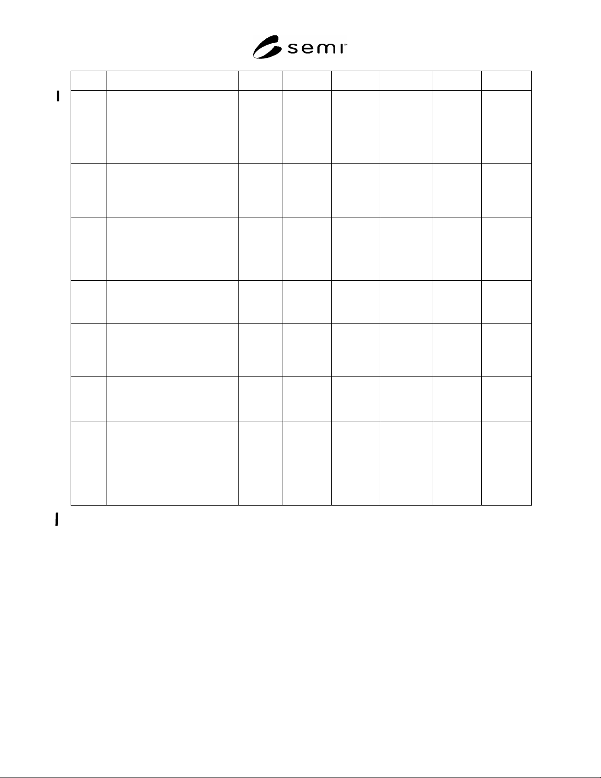
Dim Definition Option A Option B Option C Option D Option E Option F
D6 minimum distance or length of the
center exclusion volume of the
interbay transport system measured
backwards from the facial datum
plane of the interbay transport
system to allow for stocker pick up
using the secondary kinematic pins
N/A SEMI E15.1 90 mm 90 mm TBD TBD
D10 distance measured from the facial
datum plane (FDP) where the depth
of the center exclusion zone lowers
from H2 to H4 in the interbay
transport system (C,D)
N/A SEMI E15.1 150 mm or
230 mm
#1
150 mm or
230 mm
#1
150 mm or
230 mm
#1
150 mm or
230 mm
#1
H Height of the horizontal datum
plane of the interbay load port
(stocker) or interbay transport
system determined by user and
supplier
TBD
#1
and must
be
adjustable
by ± 10
mm
TBD
#1
and must
be
adjustable
by ± 10 mm
TBD
#1
and
must be
adjustable
by ± 10 mm
TBD
#1
and
must be
adjustable by
10 mm
TBD
#1
and
must be
adjustable
by 10 mm
TBD
#1
and
must be
adjustable
by 10 mm
H2 depth of exclusion zone below the
horizontal datum plane (HDP) of
the stocker load port (A,B) OR the
interbay transport system (C,D)
130 mm SEMI E15.1 100 mm 100 mm 100 mm 100 mm
H4 depth of the exclusion zone below
the horizontal datum plane (HDP)
of interbay transport system (C,D)
starting at a distance D10 from the
facial datum plane (FDP)
N/A N/A 170 mm 170 mm 170 mm 170 mm
S distance between the bilateral
datum plane of two adjacent load
ports
450 mm 505 mm N/A N/A N/A N/A
T3 height of the open volume in that it
allows the interbay transport system
to enter the stocker the transport.
This exclusion zone is occupied by
the transport itself, the maximum
height of the carrier, a clearance
above carrier, and a clearance
below the transport.
N/A N/A 800 mm or
1150 mm
#1
N/A N/A N/A
#1
User to specify which dimension (see §6).
SEMI E85-0705 © SEMI 1999, 2005 7
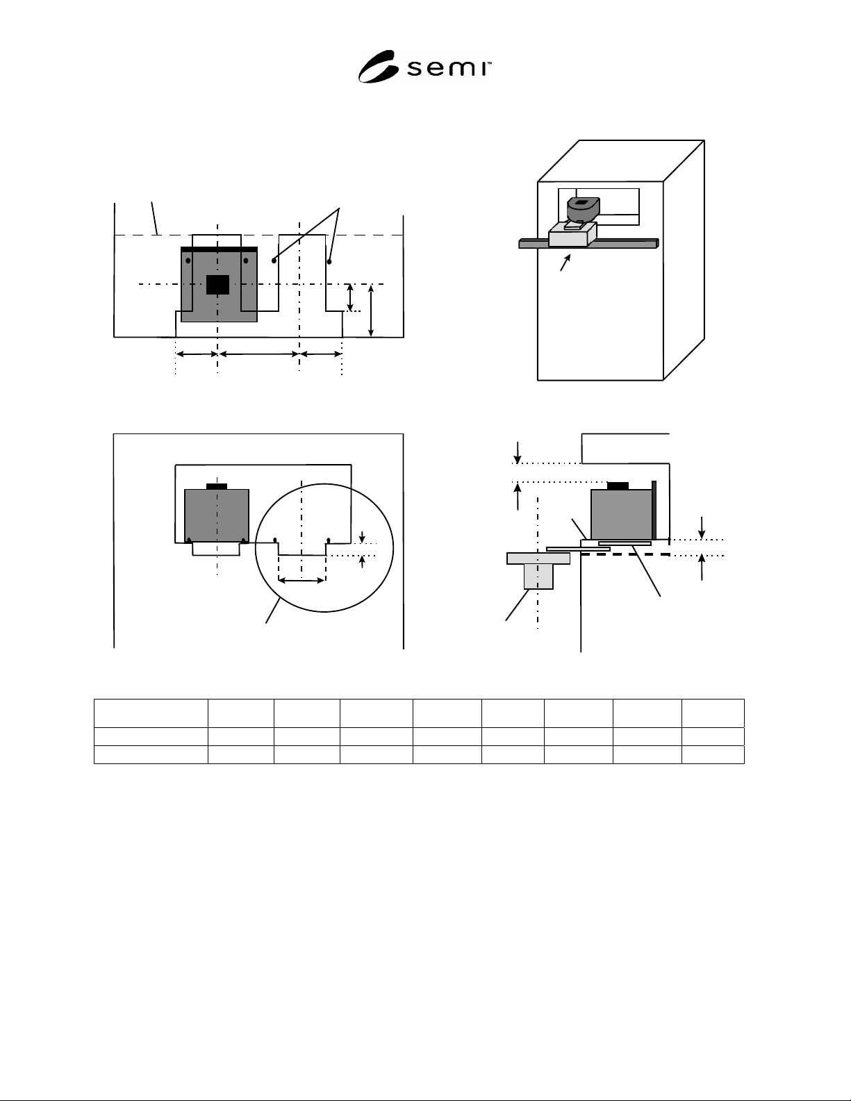
Active Transport Delivers a Carrier to an Internal Stocker Position
Option A
A
ctive
Vehicle
Top View
NOTE 1: Top view of center exclusion
volume. In Option A the Stocker uses the
primary set of kinematic pins.
D
D
1
S
A
1
A
1
Defines front view of
exclusion volume
defined in Section 7.6
(refer to Figure 7).
A
2
H
2
Front View
Stocker
Vehicle
H
2
HDP
C
3
Side View
NOTE 2: Transport
vehicle uses secondary
set of kinematic pins.
Internal boundary
of stocker
Option A H2 (min) A1 (min) A2 (range) C3 (min) D (max) D1 (max) S (min)
deg)
FOUP 130 375 213 +2/-0 150 240 150 450 0
Open Cassette 140 375 213 +2/-0 100 270 150 450 2
Figure 1
AMHS Interbay Load Port Option A
SEMI E85-0705 © SEMI 1999, 2005 8
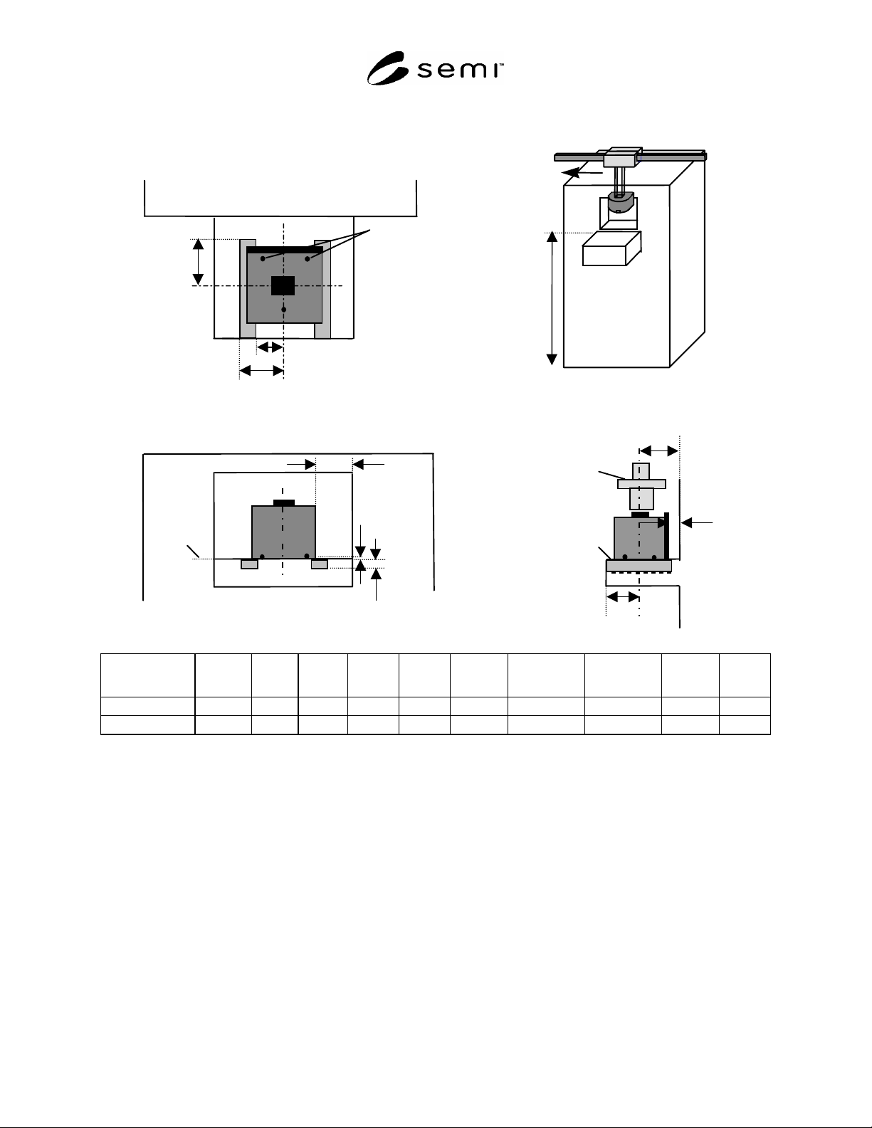
Active Transport Delivers a Carrier to an Internal Stocker Position
Stocke
r
Overhead
Transport
V
ehicle
HDP
Side View
Option B
Top View
NOTE 1:
Stocker uses
primary set of kinematic
pins.
Front View
H0
HDP
H1
C1
C2
D
D0
W1
W2
HDP
H
D1
Option B
H
#1
H0
(min)
H1
(max)
C1
(min)
C2
(min)
D0
(min)
D
(range)
D1
(range)
W1
(max)
W2
(min)
FOUP TBD 40 25 75 30 110 250 +0/-10 200 +10/-4 130 205
Open Cassette TBD 50 25 75 30 110 250 +0/-10 200 +10/-4 130 205
#1
User to specify actual dimension (see ¶ 6.2).
Figure 2
AMHS Interbay Load Port Option B