semi合集-English.pdf - 第3120页
SEMI E125-0305 © SEMI 2003, 2005 28 10.5.5 Parameter Values 10.5.5.1 Any equipment interface used in conj unction with this specification mu st provide a m eans to communicate Parameter values corresponding to the primit…
SEMI E125-0305 © SEMI 2003, 2005 27
10.5.3.3.5 EnumeratedInteger — Represents a legal value for an integer enumeration.
10.5.3.3.6 EnumeratedInteger Attribute Definition Table
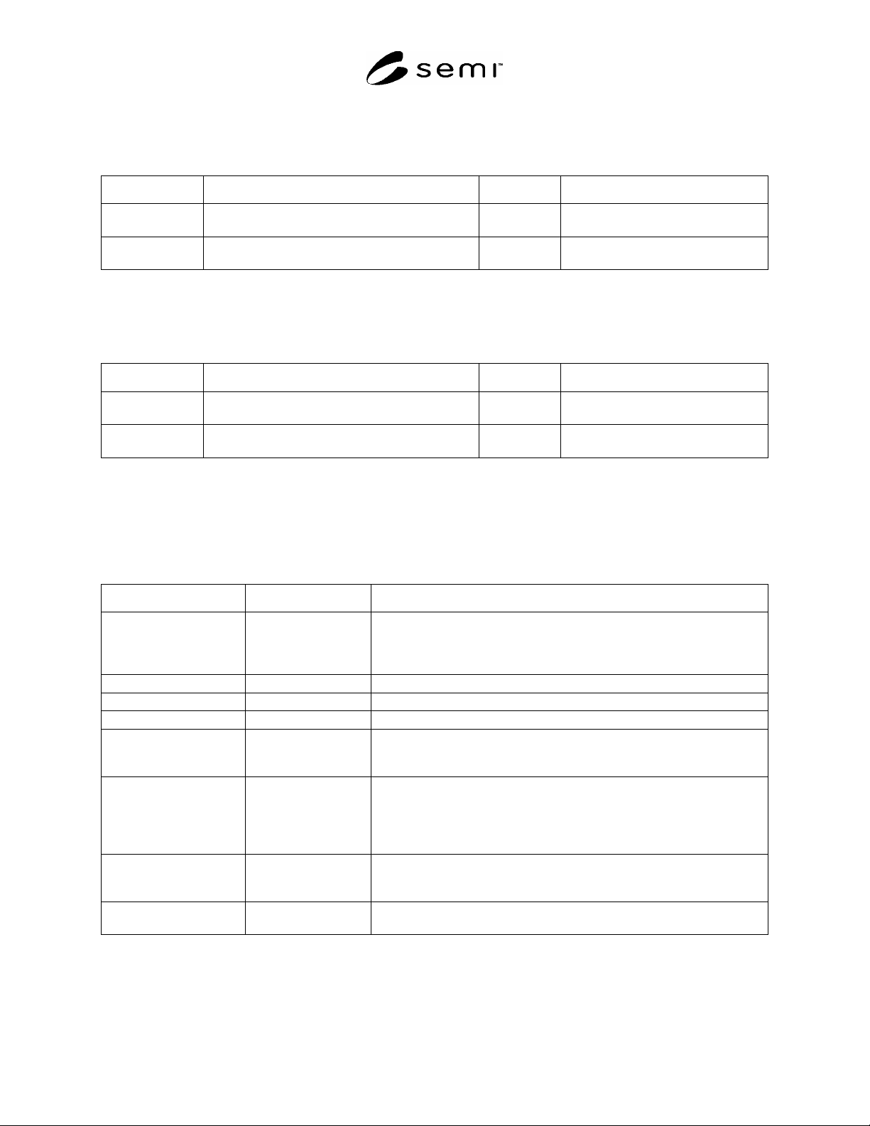
Table 45 EnumeratedInteger Attribute Definition
Attribute Name Definition Required Form
value A legal value for the enumeration. Y Integer, must be unique across all
values for this enumeration.
description A description of the meaning or purpose of this
enumeration value.
Y Text.
10.5.3.3.7 EnumeratedString — Represents a legal value for a string enumeration.
10.5.3.3.8 EnumeratedString Attribute Definition Table
Table 46 EnumeratedString Attribute Definition
Attribute Name Definition Required Form
value A legal value for the enumeration. Y Text, must be unique across all values
for this enumeration.
description A description of the meaning or purpose of this
enumeration value.
Y Text.
10.5.4 SEMI Standard Type Mapping
10.5.4.1 The following table describes how to map SEMI type terminology to the various primitive and composite
types defined in this document. This convention shall be followed when describing types that represent types
defined in a SEMI standard that is described by metadata.
Table 47 SEMI Type Mapping
SEMI Type Name Type Description to use Comments
integer, positive integer,
negative integer, non-
negative integer, non-
positive integer
IntegerType
float, floating point, real RealType
binary, bit string, byte BinaryType
boolean BooleanType
text StringType If a limitation on the number of characters is specified, the maxCharacters
attribute of the StringType class shall be set equal to the number of
characters that is supported by the supplier.
enumerated EnumeratedInteger Each enumeration shall start at value 0, and is sequenced in increments of 1
according to the order in which the enumerated values are listed in the
corresponding standard. The description field for each enumerated value
shall be equal to the text name provided for the enumerated value in the
corresponding standard.
structure StructureType Each field within the structure shall be named exactly as written in the
corresponding standard. The type of each field shall be mapped using the
conventions described in this table.
list ArrayType Lists of integers, floats, binaries, enumerateds, or structures are described as
arrays of the corresponding primitives or composite types.
SEMI E125-0305 © SEMI 2003, 2005 28
10.5.5 Parameter Values
10.5.5.1 Any equipment interface used in conjunction with this specification must provide a means to communicate
Parameter values corresponding to the primitive and composite type definitions described in this section. Since this
representation will depend on the technology used, the technology-specific specifications for such systems shall
provide a mapping between the type descriptions supported by this specification and the representation of their
corresponding values.
10.6 Units
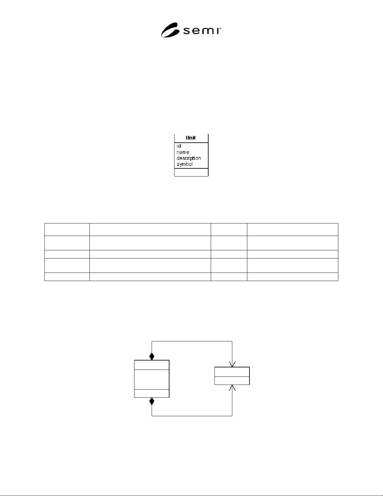
10.6.1 Figure 17 shows the Unit class that describes a specific unit used by the equipment. Any unit that can be
used for numeric data can be described with this class. This specification does not define a system of units, though
suppliers shall describe at least one unit that represents pure numbers (a “unit-less” unit).
Figure 17
Describing Units
10.6.2 Unit Attribute Definition Table
Table 48 Unit Attribute Definition
Attribute Name Definition Required Form
id The identifier for this unit. Y Text, unique across all units defined
for this equipment.
name The human-readable name for this unit. Y Text.
description A description of the unit, its dimensionality and/or
conversion factors, etc.
Y Text.
symbol The abbreviation used to represent the unit. N Text.
10.7 Exceptions
10.7.1 Figure 18 shows how to describe implemented exceptions and their associated data. The attributes and
associations of the Parameter class are not shown for clarity (see Section 10.4 for more information about
Parameters).
id
desc ript ion
severity
Exception
setData 1
0..*
clearData0. .1
0..*
Parameter
Figure 18
Describing Exceptions
SEMI E125-0305 © SEMI 2003, 2005 29
10.7.2 Exception — This class can be used to represent a warning, alarm, error, or other abnormal condition that
can be communicated by the equipment. Note that the Exception class can represent abnormal conditions whose
set/clear states are not tracked by the equipment, as well as those that are (for example, SEMI E30 alarms). For
Exceptions whose set/clear states are not tracked, no clearData is provided.
10.7.2.1 Exception Attribute Definition Table
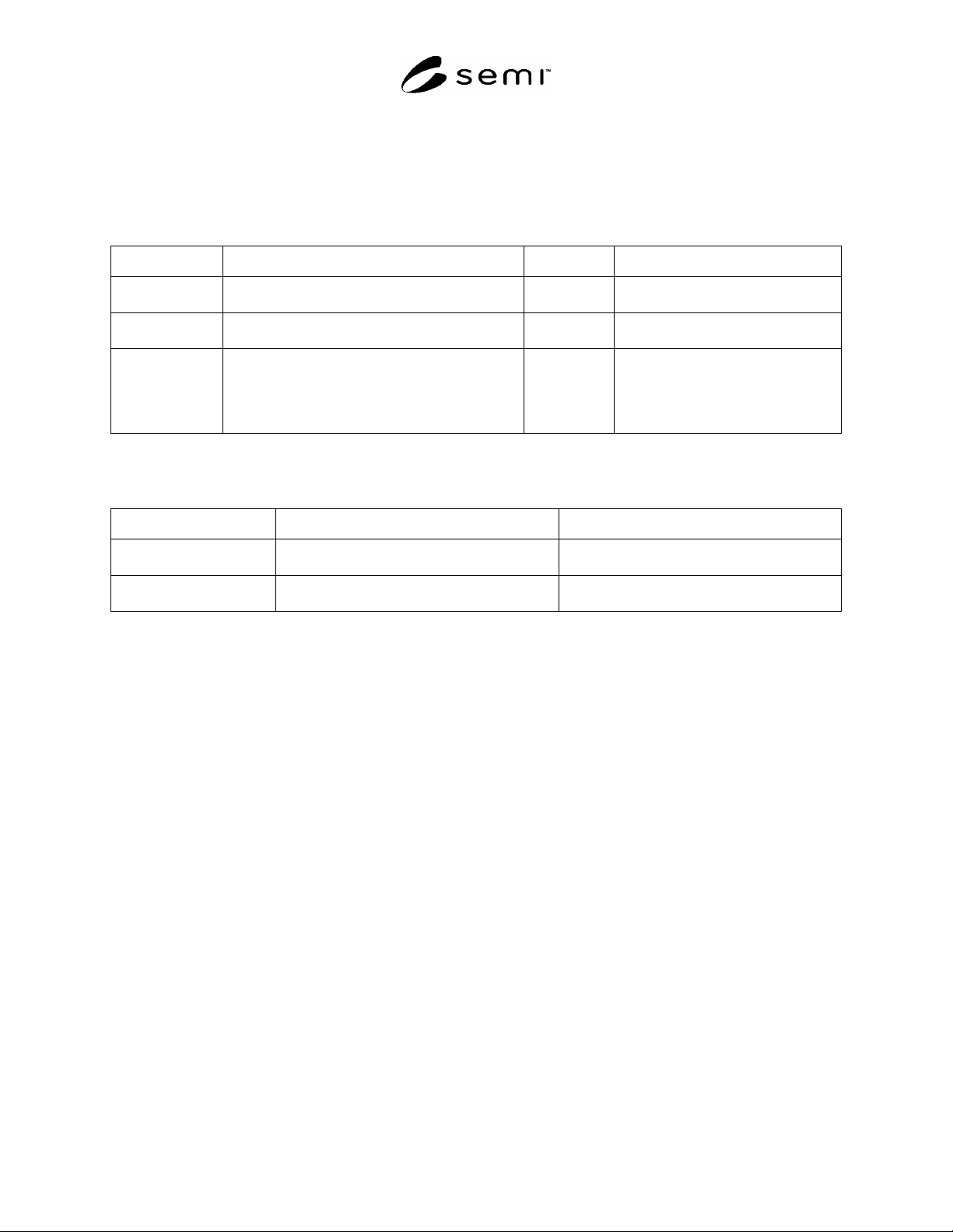
Table 49 Exception Attribute Definition
Attribute Name Definition Required Form
id Unique identifier for this exception. Y Text, unique across all exceptions
described by metadata.
description A description of the meaning of the exception when
it occurs.
Y Text.
severity Identifies the severity of this exception if it occurs. N Text, alpha characters only, no spaces.
Some examples are: “Informational”,
“Warning”, “Error”, or “Fatal”. If no
severity is defined, this attribute shall
be an empty string.
10.7.3 Exception Association Definition Table
Table 50 Exception Association Definition
Association Role Name Definition Comments
setData An ordered list of data items communicated with
the exception when it is detected.
Ordered list of zero or more elements of type
Parameter (see Section 10.4 ).
clearData An ordered list of data items communicated when
the exception has been cleared.
Ordered list of zero or more elements of type
Parameter (see Section 10.4 ).
10.8 StateMachines
10.8.1 State Machine Descriptions
10.8.1.1 Figure 19 shows how to describe the definition of a StateMachine (and its associated states and transitions)
that is implemented by the equipment. These classes can be used to describe standardized state machines, such as
those originating from SEMI standards, as well as non-standardized equipment-specific state machines. Examples
of state machines are provided in Related Information, Section R7-1.
10.8.1.1.1 The state machine description classes specified here are intended for descriptive purposes in facilitating
end-user understanding of equipment behavior that results in the generation of events. They are not intended to
provide comprehensive modeling of all semantics defined by standard state machine formalisms such as Harel or
UML. Events generated by the equipment must be defined within the context of these state machine descriptions,
even if the described state machine has not been literally implemented by the supplier. Further, this specification
does not require the supplier to provide a literal implementation of the state machines described by these classes.
10.8.1.2 A StateMachine that defines behavior that is implemented by many equipment components (for example)
need only be defined once. Each component that implements the behavior described by that StateMachine can then
refer to the events it defines through the use of the StateMachineInstance class (see Section 10.8.6). It is not
necessary to define multiple StateMachines to accommodate multiple components that each exhibit the same
behavior and generate the same events. For example, if the equipment being described has four pump components
that exhibit the same behavior, have the same underlying StateMachine, and generate the same set of events, only
one StateMachine description is necessary. Each pump component can then act as a different source (see Section
10.3.1 ) of the same set of events defined for that StateMachine, each pump executing the StateMachine
independently of the other pumps.
10.8.2 StateMachine — This class represents a collection of states and transitions that together comprise a non-
concurrent finite state machine. All StateMachines refer to a single top-level state. The top-level state can contain
zero or more substates and/or StateMachines.