semi合集-English.pdf - 第4728页
SEMI C3.55-02 00 © SEMI 2000 4 5.5.2.5 Cali bration St andards — 1–5 p p m ( mole/ mo l e) 5.5.3 Operating Procedure — (see S E M I C3, Section 6, Gas Ch ro m atography for standard proce dures). 5.5.3.1 Inject the calib…
SEMI C3.55-0200 © SEMI 20003
5.2.4 Calibration
5.2.4.1 Run titration blank consisting of 150 mL
deionized water.
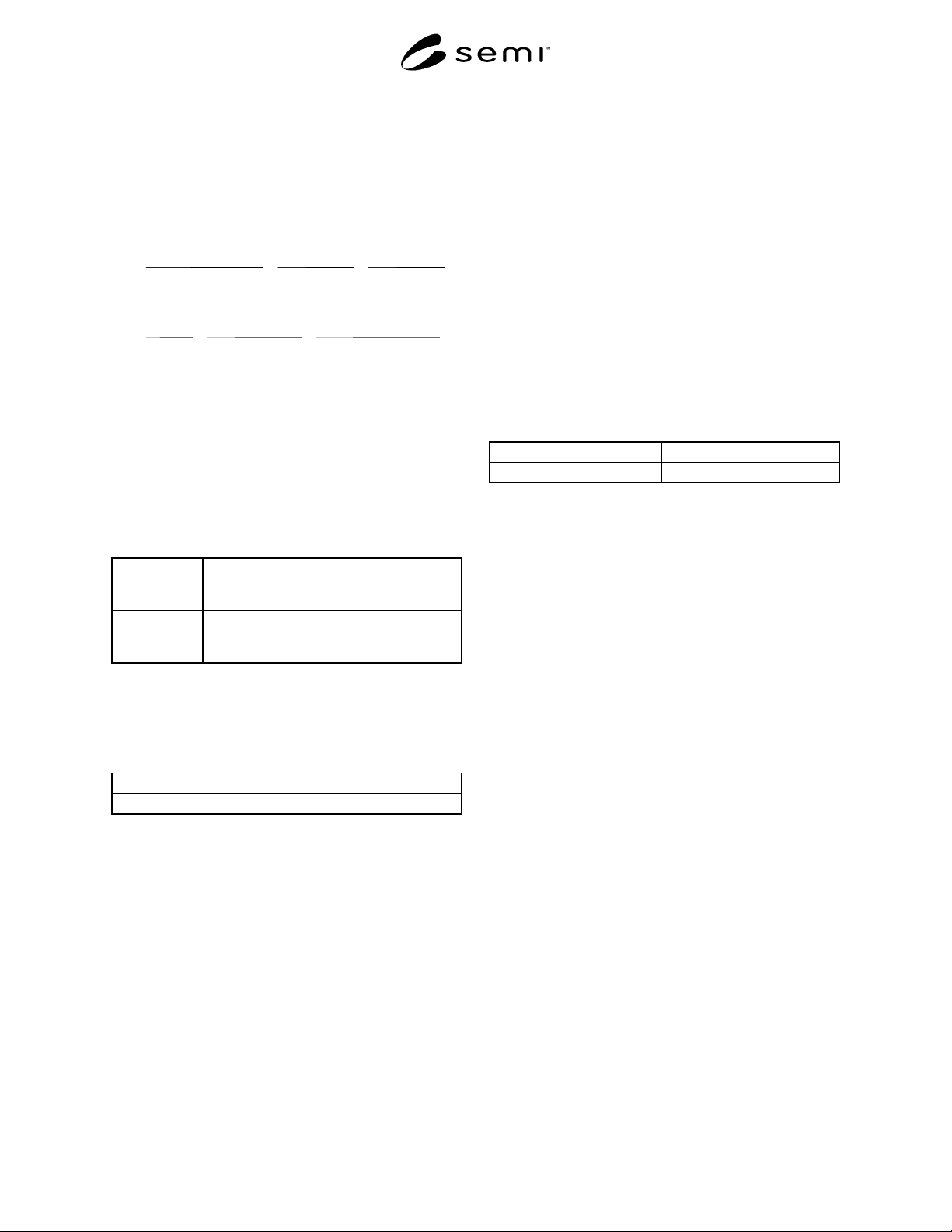
5.2.4.2 Calculate the concentration of chloride, using
the formula below. The result may not exceed the
specification in Section 2 of this standard.
mL mL
mL mL
wt.NaCl(g)
100.0mL
60.66%Cl
100%NaCl
100mL
1L
0.005l
35.453g / mole
0.082atmL/ moleK
28.316L
sample blank
standard
blank
−
−
××
−
×
××
mL mL
mL mL
wt.NaCl(g)
100.0mL
60.66%Cl
100%NaCl
100mL
1L
0.005l
35.453g / mole
0.082atmL/ moleK
28.316L
sample blank
standard
blank
−
−
××
−
×
××
×
1 × 10
6
ppm = ppm Cl-
5.3 Hydrocarbons C
2
– C
4
— This procedure is for the
determination of hydrocarbons (methane, ethane, and
propane) in silane using a gas chromatograph with a
flame ionization detector.
5.3.1 Detection Limit — 50 ppb (mole/mole)
5.3.2 Instrument Parameters
5.3.2.1 Columns:
Column 1: VZ-10, 60/80, 2 m (6.6 ft) by 3.2 mm (1/8
in) OD by 2.2 mm (0.085 in) ID stainless
steel;
Column 2: VZ-10, 60/80, 1 m (3.3 ft) by 3.2 mm (1/8
in) OD by 2.2 mm (0.085 in) ID stainless
steel;
or equivalent.
5.3.2.2 Carrier Flow — 30 mL/min nitrogen
5.3.2.3 Sample Volume — 10 mL
5.3.2.4 Temperatures:
Detector 150°C
Column Oven 45°C
5.3.3 Calibration Standards — 1 ppm (mole/mole) for
all components to be tested, balance helium.
5.3.4 Operating Procedures — (see SEMI C3, Section
6, Gas Chromatography for standard procedures).
5.3.4.1 Inject the calibration standard and sample as
described in Section 6.6 of SEMI C3. The order of
elution is methane, ethane, propane and butane (see
NOTE 2).
5.3.4.2 Compare the average peak area of the methane
peak in the calibration standard to that of the
hydrocarbons found in the silane sample being tested.
Calculate the concentrations of the analytes as
described in Section 6.8 of SEMI C3 based on the
methane response. The result shall be reported in the
unit of concentration needed and to the number of
significant digits of the variable with the least number
of significant digits. This value may not exceed that
specified in Section 2.
5.4
Hydrogen — This procedure is for the
determination of hydrogen in silane using a gas
chromatograph with a thermal conductivity detector.
5.4.1 Detection Limit — 15 ppm (mole/mole)
5.4.2 Instrument Parameters
5.4.2.1 Columns:
Molecular sieve 5A, 2.4 m (8 ft) by 6.4 mm (1/4 in) OD
by 4.7 mm (0.185 in) ID, or equivalent.
5.4.2.2
Carrier Flow — 30 mL/min argon
5.4.2.3 Sample Volume — 1.0 mL
5.4.2.4 Temperatures:
Detector 40°C
Column Oven 40°C
5.4.3 Calibration Standards — 20–100 ppm
(mole/mole), balance argon.
5.4.4 Operating Procedures — (see SEMI C3, Section
6, Gas Chromatography for standard procedures)
5.4.4.1 Inject the calibration standard and sample as
described in Section 6.6 of SEMI C3. (See NOTE 2.)
5.4.4.2 Compare the average peak area of the
hydrogen peak in the calibration standard to that of the
hydrogen found in the silane sample being tested.
Calculate the concentrations of the analytes as
described in Section 6.8 of SEMI C3 based on the
methane response. The result shall be reported in the
unit of concentration needed and to the number of
significant digits of the variable with the least number
of significant digits. This value may not exceed that
specified in Section 2.
5.5
Disiloxane, Disilane and Methyl Silane — This
procedure is for the determination of disiloxane,
disilane and methyl silane in silane using a gas
chromatograph with flame ionization detector.
5.5.1 Detection Limit — 0.1 ppm (mole/mole)
5.5.2 Instrument Parameters
5.5.2.1 Column:
28% DC-200 on Chromosorb PAW, 45/60 mesh, 14 m
(46 ft) SS, or equivalent.
5.5.2.2 Carrier Flow — 30 mL/min helium
5.5.2.3 Sample Volume — 2 mL
5.5.2.4 Temperatures — Column 60°C
SEMI C3.55-0200 © SEMI 2000 4
5.5.2.5 Calibration Standards — 1–5 ppm (mole/
mole)
5.5.3 Operating Procedure — (see SEMI C3, Section
6, Gas Chromatography for standard procedures).
5.5.3.1 Inject the calibration standard and sample as
described in Section 6.6 of SEMI C3. The order of
elution is silane matrix, methyl silane, siloxane (for
information only) and disilane. (See NOTE 2.)
5.5.3.2 Compare the average peak area of the
components being measured in the calibration standard
to that of the same analytes found in the silane sample
being tested. Calculate the concentrations of the
analytes as described in Section 6.8 of SEMI C3. The
result shall be reported in the unit of concentration
needed and to the number of significant digits of the
variable with the least number of significant digits.
This value may not exceed that specified in Section 2.
5.6
Water — This procedure is for the determination
of trace moisture (water) in silane using a vibrating
quartz hygrometer.
5.6.1 Detection Limit — 0.1 ppm (vol/vol)
5.6.2 Instrument Parameters
5.6.2.1 Flow Requirements — Set the sample pressure
and flow rate in accordance with the instrument
manufacturer’s instructions.
5.6.3 Calibration Standards — Check the hygrometer
calibration with silane using an external permeation
device. Construct a calibration curve which contains at
least three points covering the range of interest. The
standards employed will have been verified
independently on a condensation dewpoint/frostpoint
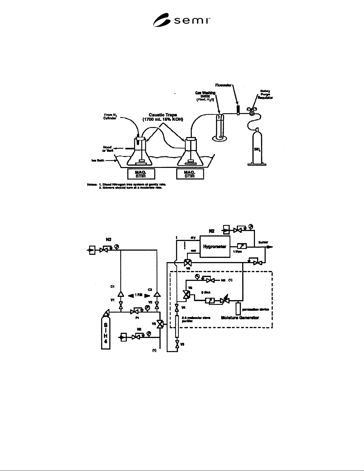
hygrometer. (See Figure 2.)
5.6.4
Operating Procedure — At the first start-up of
the hygrometer, calibrate it with moisture standards in
silane. Then check the calibration once a month and
modify the hygrometer if necessary. Direct standard to
unit with stainless lines which have been purged. Note
that silane is spontaneously flammable. Thus the
experimental set-up should be leak-free and thoroughly
purged before the introduction of silane. Obtain
representative sample of the gas to be analyzed and
direct to the unit. Wait until the equilibrium and read
the moisture content. The result may not exceed the
specification.
5.6.4.1
Construct a calibration curve with previously
verified standards. Direct standard to unit with
stainless steel lines which have been purged.
5.6.4.2 Obtain representative sample of gas to be
analyzed and direct to unit as with the standards. (See
NOTE 1.)
5.6.4.3
Construct a calibration curve and determine the
ppm moisture content in sample gas. The result may
not exceed the specification in Section 2 of this
standard.
5.7 Elemental Analysis in Deposited Layer —
Procedures for the analysis of elemental impurities in
deposited layers of polysilicon should be designated
and should be referenced from a recognized industry
standard (including but not limited to ISO, ASTM,
etc.).
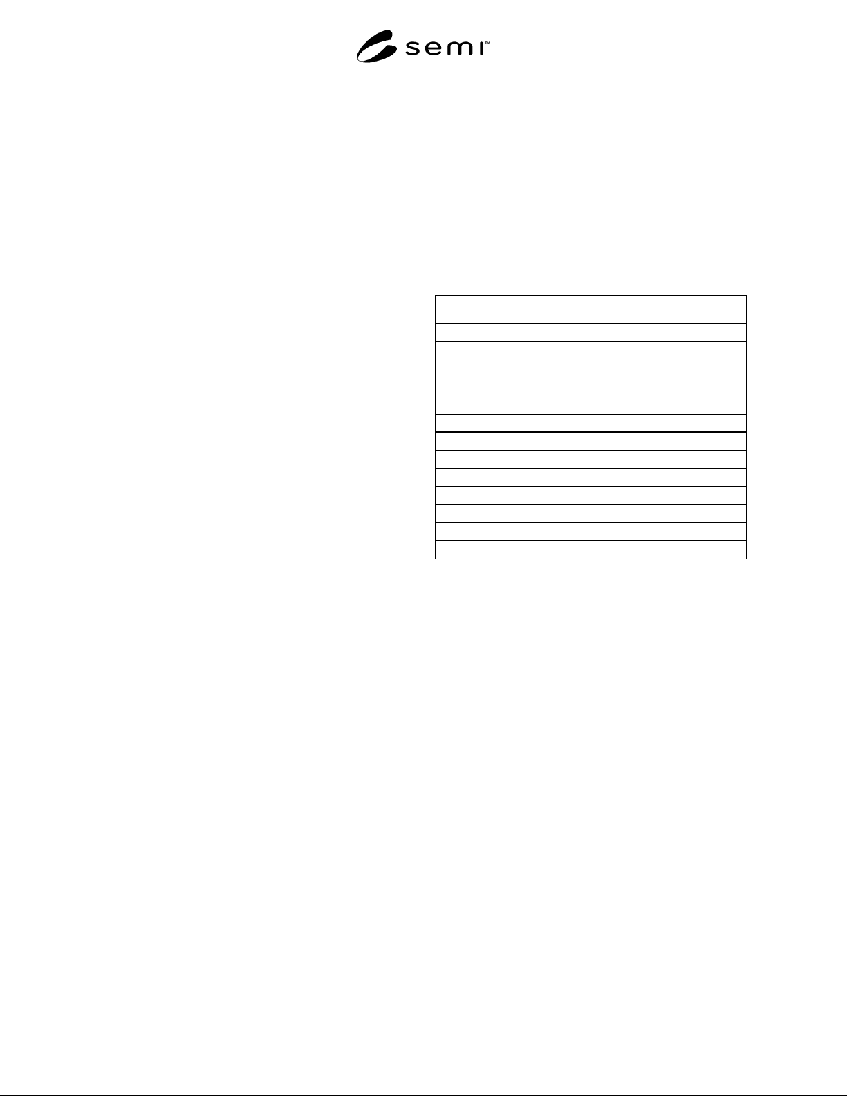
5.7.1 Typical Detection Limits
Compound Detection Limit
Carbon (C) 0.2 ppma
Oxygen (O) 0.2 ppma
Boron (B) 0.02 ppba
Aluminum (Al) 0.02 ppba
Gallium (Ga) 0.02 ppba
Phosphorus (P) 0.02 ppba
Arsenic (As) 0.02 ppba
Antimony (Sb) 0.02 ppba
Iron (Fe) 0.3 ppba
Chromium (Cr) 0.01 ppba
Nickel (Ni) 0.2 ppba
Copper (Cu) 0.02 ppba
Zinc (Zn) 0.03 ppba
5.8 Resistivity — Procedures for the measurement of
resistivity in deposited layers of polysilicon should be
designated and should be referenced from a recognized
industry standard (including but not limited to ISO,
ASTM, etc.).
NOTE 1: Before performing this or any other analytical
operation it is necessary to perform the following:
• Familiarize yourself with the products involved and the
potential hazards by consulting the MSDS's for all
hazardous substances involved and by consulting the
CGA’s “Handbook of Compressed Gases” for all gases
involved.
• Know how to safely handle and store each hazardous gas
by consulting the applicable CGA pamphlets.
• Use all necessary and applicable personal protective
equipment.
• Follow all instructions relative to the safe operation of
the equipment by consulting the LAC Safety Manual and
applicable equipment manufacturers manual(s).
It must be noted that silane is a pyrophoric gas and all sample
plumbing must be purged of air completely before introducing
silane. Extra special attention must be paid to leak checking
all connections and checking the vent plumbing to be certain
that effluents are vented properly. If there are any
SEMI C3.55-0200 © SEMI 20005
questionable connections or leaks, report this to the supervisor
immediately and do not proceed with the analysis.
NOTE 2: Introduce the calibration standard as many times as
necessary to achieve the desired precision. Detection limit
calculated on these calibrations should achieve at least that
listed for this procedure.
Figure 1
Chloride Scrubbing Apparatus
Figure 2
Moisture Analysis in Silane