semi合集-English.pdf - 第4138页
SEMI F63-00-0701 © SE MI 2001 3 Typical Line width 0.13 to 0.5 MICRONS Copper 0.02 to 0 .1 Iron 0.02 to 0.1 Lead 0.02 to 0.1 Lithium 0.02 to 0.1 Magnesi um 0.02 to 0.1 Mangan ese 0 .02 to 0.1 Nickel 0.02 to 0.1 Potassium…
SEMI F63-0701 © SEMI 2001 2
5 Use of the Guidelines
5.1 Sampling methods and contamination control are
of paramount importance when attempting to measure
the listed parameters at the levels specified.
5.2 The quality of the data measured will depend on
which testing method and calibration techniques are
used. Consequently, trends observed in the values may
be more meaningful than absolute values.
6 Units
6.1 Parts per billion (ppb) is equivalent to ng/mL or
µg/L.
6.2 Parts per million (ppm) is equivalent to mg/L.
6.3 Micron is a unit of length equal to one millionth of
a meter, or one thousandth of a millimeter.
6.4 Colony Forming Units (CFU) is a measurement of
bacteria organisms.
7 Description of Parameter Tests
NOTE 2: Since SEMI Guidelines do not require analytical
data or methods to support them, the recommendation of
specific analytical methods are only for informational
purposes. Alternative methods may also be applicable.
7.1 Resistivity (megohm-centimeters or Mohm–cm)
7.1.1 Resistivity (conductivity) is only measured
accurately with on-line instrumentation.18.25 MOhm is
the theoretical upper limit for pure water at 25
°
C.
7.2 Total Oxidizable Carbon (TOC) (ppb)
7.2.1 Involves oxidation of organic materials and
detection of carbon dioxide produced by the reaction, as
measured in conductivity or infrared photometry.
7.3 Dissolved oxygen (ppb) is onl y measured
accurately with on-line instrumentation.
7.4 Particulate Matter (Particles/L )
7.4.1 On-line methods using laser technology are
recommended for accurate trend analysis.
7.5 Bacteria (CFU/L)
7.5.1 Triplicate samples are cultured based on the
ASTM method F 1094 using a minimum sample size of
1L.
7.6 Silica
7.6.1 Total Silica (ppb) may be measured by Graphite
Furnace Atomic Absorption Spectrophotometry
(GFAAS), Inductively-Coupled Plasma Atomic
Emission Spectroscopy (ICP-AES) or Inductively
Coupled Plasma Mass Spectroscopy ( ICP-MS).
7.6.2 Dissolved Silica (ppb as SiO
2
) may be measured
by heteropoly blue photometry or by Ion
Chromatography.
7.7 Ions and Metals (ppb)
7.7.1 Many anions and cations may be determined
using Ion Chromatography.
7.7.2 Up to 68 metals may be determined by GFAAS,
ICP-AES, or ICP-MS. Most typically measured metals
are shown in Table 1.
8 Parameters and Typical Concentrations
8.1 Table 1 lists each parameter with its range of
performance.
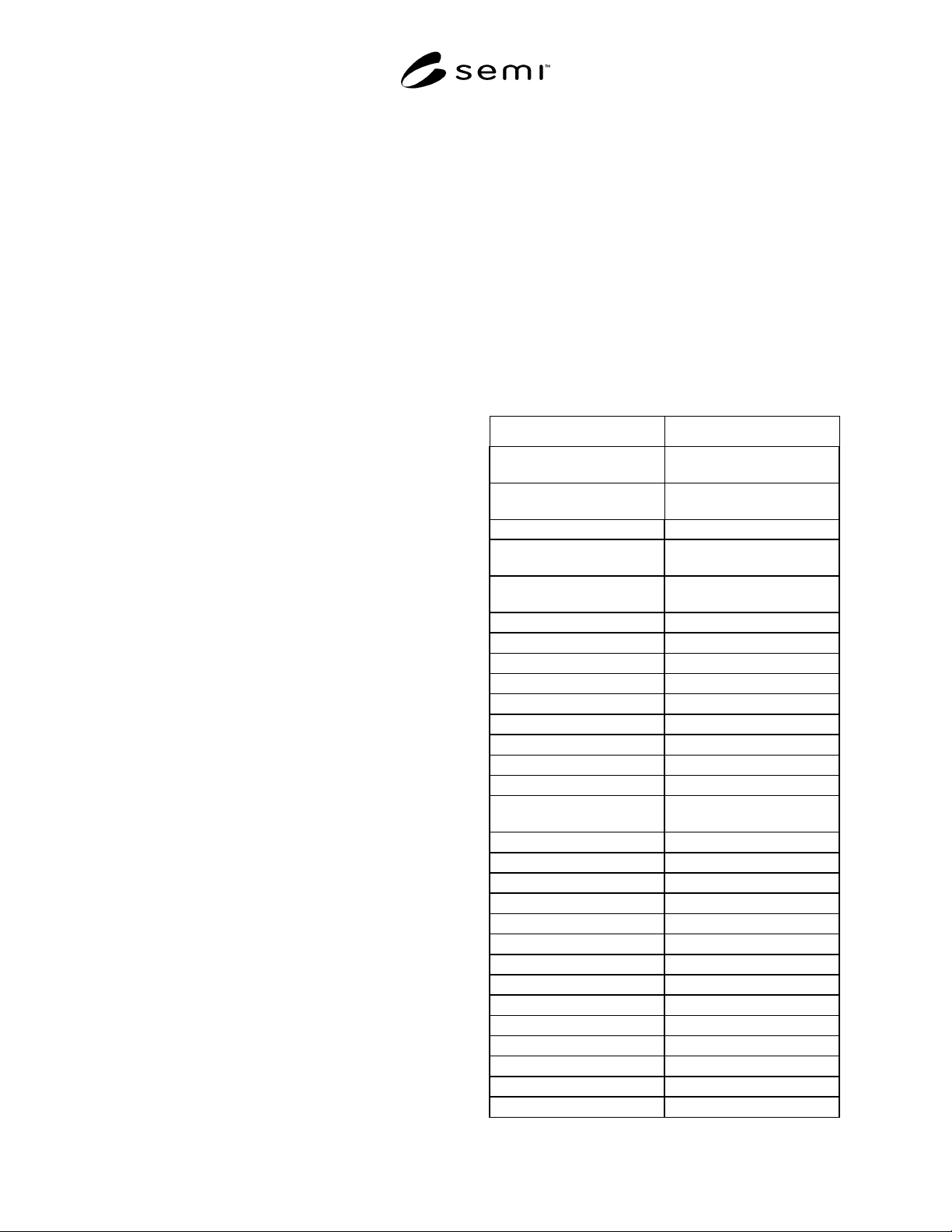
Table 1 Parameters and Range of Performance
Typical Linewidth 0.13 to 0.5 MICRONS
PARAMETER RANGE OF
PERFORMANCE
Resistivity on-line @ 25
°
C
(Mohm–cm)
17.9 to 18.2
TOC on-line (ppb)
1 to 5
Dissolved Oxygen on-line
(ppb)
0.5 to 20
On-line Particles/L
(micron range)
0.05–0.1 100 to 1000
0.1–0.2 50 to 500
0.2–0.3 20 to 100
0.3–0.5 10 to 50
> 0.5 0 to 4
Bacteria (CFU/L)
1 L Sample 0 to 5
Silica
Silica - total (ppb) 0.5 to 3
Silica - dissolved
(ppb as SiO
2
)
0.2 to 1
Ions & Metals (ppb)
Ammonium 0.02 to 0.1
Bromide 0.02 to 0.1
Chloride 0.02 to 0.1
Fluoride 0.02 to 0.1
Nitrate 0.02 to 0.1
Nitrite 0.02 to 0.1
Phosphate 0.02 to 0.1
Sulphate 0.02 to 0.1
Aluminum 0.02 to 0.1
Barium 0.02 to 0.1
Boron 0.02 to 20
Calcium 0.02 to 0.1
Chromium 0.02 to 0.1

SEMI F63-00-0701 © SEMI 20013
Typical Linewidth 0.13 to 0.5 MICRONS
Copper 0.02 to 0.1
Iron 0.02 to 0.1
Lead 0.02 to 0.1
Lithium 0.02 to 0.1
Magnesium 0.02 to 0.1
Manganese 0.02 to 0.1
Nickel 0.02 to 0.1
Potassium 0.02 to 0.1
Sodium 0.02 to 0.1
Strontium 0.02 to 0.1
Zinc 0.02 to 0.1
NOTICE: SEMI makes no warranties or
representations as to the suitability of the standards set
forth herein for any particular application. The
determination of the suitability of the standard is solely
the responsibility of the user. Users are cautioned to
refer to manufacturer’s instructions, product labels,
product data sheets, and other relevant literature
respecting any materials mentioned herein. These
standards are subject to change without notice.
The user’s attention is called to the possibility that
compliance with this standard may require use of
copyrighted material or of an invention covered by
patent rights. By publication of this standard, SEMI
takes no position respecting the validity of any patent
rights or copyrights asserted in connection with any
item mentioned in this standard. Users of this standard
are expressly advised that determination of any such
patent rights or copyrights, and the risk of infringement
of such rights, are entirely their own responsibility.
Copyright by SEMI® (Semiconductor Equipment and Materials
International), 3081 Zanker Road, San Jose, CA 95134. Reproduction o
f
the contents in whole or in part is forbidden without express written
consent of SEMI.

SEMI F64-0701 © SEMI 20011
SEMI F64-0701
TEST METHOD FOR DETERMINING PRESSURE EFFECTS ON
INDICATED AND ACTUAL FLOW FOR MASS FLOW CONTROLLERS
This specification was technically approved by the Global Facilities Committee and is the direct
responsibility of the North American Facilities Committee. Current edition approved by the North American
Facilities Committee on April 30, 2001. Initially available at www.semi.org May 2001; to be published July
2001.
1 Purpose
1.1 The purpose of this document is to define a
method for characterizing a MFC being considered for
installation into a gas distribution system. This method
will quantify the effect of transient and steady state
inlet and outlet pressure conditions on the performance
of the MFC.
1.2 This document provides a com mon basis for
communication between manufacturers and users
regarding testing and describing MFC pressure effects.
2 Scope
2.1 This test method measures the upstream (inlet) and
downstream (outlet) transient pressure influences on
indicated and actual flow.
2.2 This test method yields the res ults of actual output
flow versus MFC set-point and indicated flow as
influenced by steady state inlet pressure.
2.3 This test method applies to MF Cs with maximum
flow ranges of up to 1000 sccm.
NOTE 1: Due to the higher sensitivity of lower flow rate
MFC’s when pressure transients occur, the flow range for this
document is limited to 1000 sccm.
2.4 This standard does not purport to address safety
issues, if any, associated with its use. It is the
responsibility of the users of this standard to establish
appropriate safety health practices and determine the
applicability or regulatory limitations prior to use.
3 Limitations
3.1 This test method is limited to a nalyzing the effect
of pressure on performance characteristics of MFCs and
is not a verification of the state of calibration, linearity,
or accuracy.
3.2 This test method does not address pressures in
excess of the DUT’s maximum working pressure as
specified by the manufacturer.
3.3 This test method is limited to r easonable pressure
transients; i.e., fluctuations that are otherwise tolerated
by common semiconductor process equipment.
3.4 This test method does not address operational
influences outside of the manufacturer’s published
limitations.
3.5 This test method does not addr ess the effects of
interruptions of the gas supply.
4 Referenced Standards
4.1 None.
5 Terminology
5.1 Definitions
5.1.1 actual flow — flow as indicate d by flow
standard (see Figures 1 and 2).
5.1.2 indicated flow — flow as indic ated by the device
under test (DUT).
5.1.3 ramp — constant rate of change in pressure
(dp/dt = k).
5.1.4 stability — the ability of a con dition to exhibit
only natural, random variation in absence of unnatural,
assignable cause variation.
5.1.5 step change — an exponential step in pressure
with a time constant of one second or less.
5.2 Abbreviations and Acronyms
5.2.1
δ
M — deviation of mass of material relative to
steady-state mass delivery.
5.2.2
∆
P — change in pressure with respect to time
5.2.3
∆
Q — steady state deviation of actual flow
during inlet pressure ramp from that while inlet
pressure is constant.
5.2.4
δ
Q
-
— maximum negative dev iation of actual
flow from nominal.
5.2.5
δ
Q
+
— maximum positive dev iation of actual
flow from nominal.
5.2.6
τ
— pneumatic time constant
5.2.7 DUT — device under test
5.2.8 MFC — mass flow controller
5.2.9 MV — metering valve