semi合集-English.pdf - 第7054页
SEMI S17-0701 © SEMI 2001 2 4 Referenced Stand ards NOTE 2: Unless otherwise indicated, all docu ments cited shall be t he latest p ublished v ersions. 4.1 SEM I Standar ds SEMI E15.1 — Specif ication for 300 mm Tool Loa…

SEMI S17-0701 © SEMI 20011
SEMI S17-0701
SAFETY GUIDELINE FOR UNMANNED TRANSPORT VEHICLE (UTV)
SYSTEMS
This safety guideline was technically approved by the Global Environmental Health and Safety Committee
and is the direct responsibility of the Japanese Environmental Health and Safety Committee. Current edition
approved by the Japanese Regional Standards Committee on February 1, 2001. Initially available at
www.semi.org April 2001; to be published July 2001.
NOTICE: Paragraphs entitled “NOTE:” are not an
official part of this document and are not intended to
modify or supersede the official guideline.
1 Purpose
1.1 These guidelines are intended as a set of
environmental, safety, and health considerations for
unmanned transport vehicle (UTV) systems. UTV
systems are used to automate the movement of material
within semiconductor factories. Unmanned transport
vehicle systems include both floor-traveling vehicle
systems and space-traveling vehicle systems.
2 Scope
2.1 This guideline applies to UTV systems used in
semiconductor manufacturing.
2.2 This guideline addresses both floor-traveling and
space-traveling UTV systems. Floor-traveling vehicle
systems include automatic guided vehicle (AGV)
systems and rail guided vehicle (RGV) systems. Space-
traveling vehicle systems include interbay overhead
transport vehicle systems and intrabay overhead hoist
transport vehicle (OHT) systems.
2.3 Evaluations for conformance to this document
should include all equipment that is provided by the
UTV system supplier including separate items such as
rails, control panels, power panels, and any other type
of equipment necessary for operation of the unmanned
transport vehicles.
2.4 This safety guideline does not purport to address
all of the safety issues associated with its use. It is the
responsibility of the users of this guideline to establish
appropriate safety and health practices and determine
the applicability of regulatory limitations prior to use.
2.5 This document contains the following sections:
• Purpose
• Scope
• Limitations
• Referenced Standards
• Terminology
• Equipment Evaluation
• Clearances and Interfaces
• Emergency Shutdown
• Manual Operation
• Vehicle Travel
• Material Protection
• Load/Unload Operation
• Hazard Indicators
• Hazardous Materials
• Related Documents
3 Limitations
3.1 This safety guideline may have only limited
application to vehicles without on-board power (direct
or induced) such as primary-grounded linear–motor-
driven overhead transport vehicle systems used for
interbay transport. Determinations of applicability
should be made by section when evaluating such
systems.
3.2 This safety guideline does not address rail-guided
or robotic mechanisms included as part of
semiconductor processing equipment. This type of
equipment should be evaluated as part of the processing
equipment per SEMI S2.
3.3 Person Guided Vehicles (PGVs) are not unmanned
vehicles, therefore PGVs are not addressed by this
standard.
3.4 This document does not supersede international,
national or local codes, regulations and laws, which
may impose separate requirements for assessing the
safety of installations.
NOTE 1: Users should provide information to UTV suppliers
about regulations for the location of use.

SEMI S17-0701 © SEMI 2001 2
4 Referenced Standards
NOTE 2: Unless otherwise indicated, all documents cited
shall be the latest published versions.
4.1 SEMI Standards
SEMI E15.1 — Specification for 300 mm Tool Load
Port
SEMI E23 — Specification for Cassette Transfer
Parallel I/O Interface
SEMI E84 — Specification for Enhanced Carrier
Handoff Parallel I/O Interface
SEMI S2 — Environmental, Health, and Safety
Guideline for Semiconductor Manufacturing Equipment
SEMI S8 — Safety Guidelines for Ergonomics
Engineering of Semiconductor Manufacturing
Equipment
4.2 ANSI Standard
1
ANSI/RIA R15.06 — Industrial Robots and Robot
Systems - Safety Requirements
4.3 CENELEC Standards
1
EN775 — Manipulating Industrial Robots – Safety
4.4 ISO Standards
2
ISO 10218 — Manipulating Industrial Robots – Safety
5 Terminology
5.1 automated operation — system operation under
full pre-programmed control of the computer controller.
5.2 automatic guided vehicle (AGV) — a floor based
vehicle, with or without robotic manipulators, used for
transporting loads and operating without the need for
assistance by factory personnel. AGVs travel without
mechanical guidance.
5.3 bumper — a shock absorber for a UTV. A
bumper is typically equipped with a contact switch or
sensor on it. And if the bumper switch or sensor is
activated, the UTV will stop immediately.
5.4 EMO — an actuator (e.g., button) which, when
activated, places the equipment into a safe shutdown
condition, without generating any additional hazard to
personnel or the facility.
5.5 E-Stop — emergency stop feature provided to stop
all moving parts but not necessarily isolating or
controlling all energy sources.
1 American National Standards Institute, 11 West 42nd St., 13th
Floor, New York, NY 10036
2 International Organization for Standardization (ISO), 1 rue de
Varembe, Case postale 56, CH-1211 Geneve 20, Switzerland
5.6 end user customer — as related to UTVs, the
company operating the factory in which the UTVs are
installed.
5.7 fault-tolerant — designed so that a reasonably
foreseeable single point failure does not result in an
unsafe condition.
5.8 floor-traveling vehicle — a vehicle that
automatically travels on the factory floor to a specified
station where a load/unload operation is performed
automatically or manually. Floor-traveling vehicles
include automatic guided vehicles (AGV) and rail
guided vehicles (RGV).
5.9 hoist — the assembly on a space-traveling vehicle
that performs the load/unload operation by transferring
a load [e.g., carrier(s), pod(s)] to and from an overhead
vehicle.
5.10 interbay transport — moveme nt of loads [e.g.,
carrier(s), cassette(s), reticle(s)] between functional
work areas or bays.
5.11 intrabay transport — movement of loads [e.g.,
carrier(s), cassette(s), reticle pod(s)] within a functional
work area or bay.
5.12 load — load is the object to be transported by
UTV. Load includes a carrier (cassette, box, pod, etc.)
and its contents.
5.13 load/unload operation — the action necessary to
move a load [e.g., carrier(s), cassette(s) reticle pod(s)]
to and from a vehicle. This operation may involve
hoisting, manual, or robotic manipulation to transfer
loads between a vehicle and semiconductor
manufacturing equipment (such as process equipment
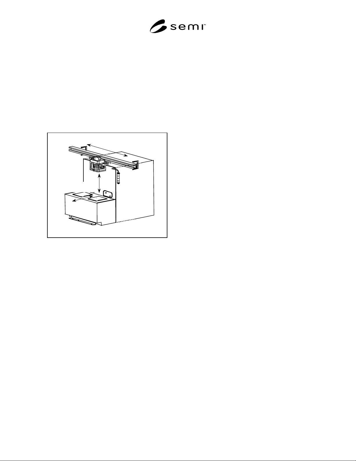
or stockers). See Figure 1.
5.14 manual operation — defined as any control
outside of automated operation.
5.15 overhead hoist transport (OHT) — a rail guided
vehicle and hoist used to transport material above the
factory floor over the heads of factory personnel.
5.16 rail guided vehicle (RGV) — a floor-based
vehicle, with or without robotic manipulators, used to
transport loads and operating on a guide rail without the
need for assistance by factory personnel.
5.17 space-traveling vehicle — a vehicle that
automatically travels through space, such as in the
region just below a factory ceiling, to a specified station
where a load/unload operation is performed
automatically or manually. Space-traveling vehicles
include interbay overhead transport vehicles and
intrabay overhead hoist transport vehicles (OHT).
SEMI S17-0701 © SEMI 20013
5.18 station — the destination point where an
unmanned transport vehicle is programmed to stop for
load/unload operation (also known as a control point).
5.19 travel — the automated motion of a vehicle along
a rail or programmed path from one station to another
station. Travel does not include load/unload operation.
See Figure 1.
5.20 unmanned transport vehicle (UTV) — a vehicle
used to automate the movement of production material
within semiconductor factories. There are two types of
UTVs, floor-traveling vehicles and space-traveling
vehicles.
Travel
Station to Station
Load/Unload
Overhead or Floor Vehicle
Figure 1
Delineation of Travel vs. Load/Unload
6 Equipment Evaluation
6.1 Equipment Evaluation for both Floor-Traveling
and Space-Traveling Vehicles — All UTV equipment
should be evaluated against the following referenced
provisions.
6.2 All UTV equipment should be evaluated against
appropriate sections of SEMI S2 for environmental,
safety, and health considerations.
6.2.1 Evaluations to the provisions in the following
sections of SEMI S2 are applicable to declare
conformance to this document.
a) Electrical Design
b) Emergency Shutdown
c) Automated material handlers (This Automated
material handlers section only applies to the
robotics portion of UTV equipment, when
provided.)
d) Hazard Warning Labels
e) Seismic Protection
f) Documents provided to User
6.2.2 At the discretion of the evaluator, additional
provisions in SEMI S2 may be considered for
evaluation based on the functionality of the UTV
equipment.
6.3 All UTV equipment should be evaluated against
SEMI S8 for ergonomic considerations.
6.4 All UTV equipment should be evaluated against
the applicable Electro Magnetic Compatibility (EMC)
regulations of the proposed installation site.
6.5 In addition to the provisions referenced in Section
6.1, UTV equipment should also be evaluated to the
provisions contained in the following sections of this
document.
7 Clearances and Interfaces
7.1 Body Shape of both Floor-Traveling and Space-
Traveling Vehicles — The body of a UTV should be
free of any dangerous parts such as sharp edges and
protrusions. The UTV body surface should have a
smooth finish.
7.2 Minimum Clearance for Floor-Traveling Vehicles
— Where passageways are used for emergency egress,
they should be provided on at least one side of the
UTV. International, national or local codes,
regulations, and laws should be used to determine
passageway width.
7.3 Minimum Clearance for Space-Traveling Vehicles
— The lowest part of the space-traveling vehicle,
including the load, should maintain a minimum
clearance of 2135 mm (7 feet) above the walking floor.
NOTE 3: Some end user customers may request a higher
minimum clearance, or a minimum clearance between the
space-traveling vehicle and the top of other equipment, to
accommodate clearances specified by SEMI E15.1.
7.4 Interfaces with Building Structures for both Floor-
Traveling and Space-Traveling Vehicles
UTV
suppliers should provide for optional vehicle interfaces
with building structures like doors, elevators, and walls.
7.4.1 If UTVs are required to operate in conjunction
with building structures, such as automatic doors or
elevators, UTVs should be capable of communicating
with the facility to assure safe door opening/closing.
7.4.2 If it is necessary for a UTV to travel through a
building firewall, the firewall pass through should be
specified and/or designed to maintain the fire rating of
the wall in the event of a fire.