semi合集-English.pdf - 第2297页
SEMI E81-0600 © 1999, 2 000 34 overall maintenance job supervision functions (see Section 7.3.3.5), and the various resource t y pes implement these functions in the Equipment Tracking and M ainte nanc e, Dur able s Ma n…
SEMI E81-0600 © 1999, 200033
Resource Control
Task
Specification Material
MESFactory
Area
Production
Machine
Process
Resource
Factory Job
Area Job
Production
Machine
Job
Process
Resource
Job
Order,
OrderItem
ProductGroup,
Lot, LotFamily,
Inventory Region
Inventory Region,
Process Group
Process
Group
Process
Resource
Group
Product Request,
ProductSpec.,
ProcessDefinition
Process Operation
Sequence
Process Operation
Sequence
Process Operation
Spec,
Process Operation
Enterprise Job
Enterprise
Product
Management
Specification
Recipe
Management
Factory
Operations
Process Machine,
Advanced Process Control
Factory
Resource,
Tracking and
Maintenance
Equipment,
Durables and
Consumables
Resource, Tracking
and Maintenance
Process Automation
(out of scope)
Enterprise
(out of scope)
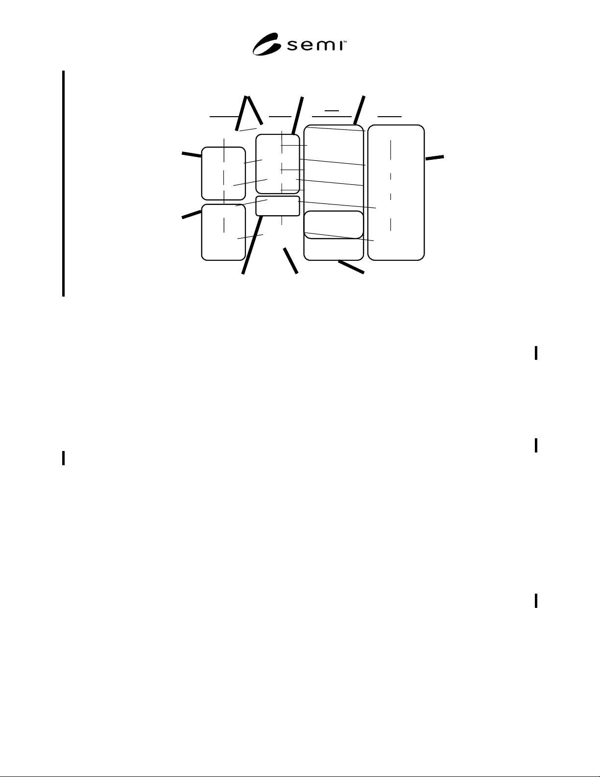
Figure 20
Integrated Hierarchical Job Control
7.3.4.9.2 As Section 7.3.3.3 describes, each of these
job control views shows a job supervision function that
performs the tasks for each level of the factory resource
hierarchy.
7.3.4.9.2.1 Factory Job Supervision: Factory
Operations satisfies enterprise product requests. It
releases material and creates Factory Jobs which drive
material work-in-progress through its process flow. The
Factory Job Executor requests, schedules, monitors and
coordinates supporting jobs: production machine jobs,
transport jobs, maintenance jobs, etc.
7.3.4.9.2.2 Area Job Supervision: This optional level
serves Factory Operations and is responsible for
multiple machine activities (areas may map to bays, cell
controllers, linked lithography, etc.). This level is not
required, but is available for organizing large factories.
Area job supervision could support factories that have a
factory within a factory model with separate but
integrated operations management for separate units of
manufacturing capacity. It could also support factories
transitioning from legacy systems, with parts of the
factory under a CIM Framework-conformant MES and
other parts under a legacy MES that is fronted or
wrapped by a CIM Framework conformant Area Job
Supervisor component. Another example could be a
factory that provides a pseudo-cluster cell controller to
group stand-alone process equipment into an integrated
workcell that behaves like a cluster tool. The CIM
Framework does not specify separate Area Job
Supervision interfaces. These functions are met by the
Production Machine Job interfaces with no changethe
same interface serves both functional roles. Areas
typically receive a sequence of process jobs as a request
(implemented by requesting lower-level process jobs
and material transport jobs), whereas simple machines
usually receive a single process job (implemented
through direct interaction with process equipment).
7.3.4.9.2.3 Machine Job Supervision: This level lies
within the CIM Framework Production Machine
component. It accepts activities that apply to a single
Machine. It delegates work directly to the physical
equipment, either through some equipment interface
driver or directly through the GEM/SECS interface.
7.3.4.9.2.4 Transport Job Supervision: This level lies
within the Material Transport and Storage component.
It takes requests to move material from one location to
another. While the CIM Framework provides for layers
of Transport Job Supervisors in a complex interbay and
intrabay material handling system, today’s typical
installation has a single material handling system
controller (a single Transport Job Supervisor). Complex
production machines with internal material handling
and storage may also be Transport Job Supervisors.
7.3.4.9.2.5 Maintenance Job Supervision: Maintenance
is a preventive (scheduled) or reactive (repair on
failure) activity on specific resources (machines,
durables, etc.) using labor resources and materials.
Maintenance job progress is reported and tracked and
maintenance job history is stored. The generic Resource
Tracking and Maintenance component defines the
SEMI E81-0600 © 1999, 2000 34
overall maintenance job supervision functions (see
Section 7.3.3.5), and the various resource types
implement these functions in the Equipment Tracking
and Maintenance, Durables Management, Consumables
Management, and Factory Labor components.
7.3.4.9.2.6 Advanced Process Control (APC): APC
includes lengthy calculation activities that may not
succeed and which impact the performance of other
jobs. For example, an algorithm may not converge, a
sensor may emit bad data, or process recipes and job
specifications may be modified. The CIM Framework
APC component leverages the overall job architecture,
where control strategies and scripts are the job
specifications, sensor analysis and control execution
environments are scheduled resources, and the state of
process specifications (machine settings, modified
process flows) are the result of APC job execution.
7.3.4.9.2.7 Enterprise and Process Resource: The job
control hierarchy of Figure 19 provides interfaces to the
enterprise at the top level and the equipment at the
bottom level. The enterprise level is the requestor of
work for the factory. Enterprise control is outside the
MES functional scope of the CIM Framework. The
equipment level is also outside the scope of control of
the CIM Framework. It is usually implemented by
process controllers embedded in or piggyback on
equipment. The equipment level is modeled for the
MES to allow process data to be collected and
organized for specific equipment resources such as a
specific chamber in a cluster tool.
7.3.4.10 Job History
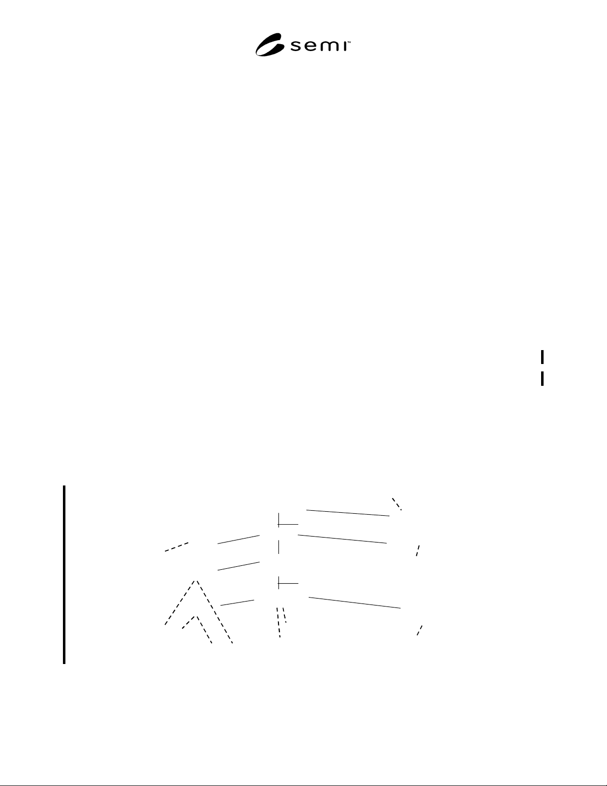
7.3.4.10.1 Any entity can have an associated CIM
Framework History. The CIM Framework defines some
specific named histories, as Figure 21 illustrates.
Product-oriented data is captured in production history
associated with the material hierarchy and is used, for
example, for material traceability and defect analysis.
Process-oriented data is captured in process history
associated with the job supervision hierarchy and is
used, for example, for run-to-run process control.
Equipment and other resource-oriented data is captured
in resource history associated with the resource
hierarchy and is used, for example, for preventive
maintenance and warranty tracking.
7.3.4.10.2 As jobs are executed (and possibly broken
down into sub-tasks as shown in Figure 12), their
results are captured as various types of histories. For
example, an Area Job’s history may be captured within
an InventoryRegionHistory. A Resource Level Job’s
history may be captured within an E10Perform-
anceHistory or within a ResourceMaintenance-
LogHistory.
7.3.4.11 Task Specification and Workflow
7.3.4.11.1 The specification of a task takes various
forms. For Factory Jobs, the specification is the process
flow defining the process steps to transform material
into products. For Production Machine Jobs, the
specification is the specific steps in the process flow
that this production machine is to perform, along with
process recipes. For Transport Jobs, the specification
defines the destination location for the material
transport group. For maintenance jobs, the specification
defines the specific maintenance tasks for the resource.
For advanced process control jobs, the specification
defines a script that includes the sensor processing and
algorithm steps of a control strategy.
ProcessResourceHistory
(sequence of ProcessRun data)
productionHistory
E10PerformanceHistory
ControlDatabase
ControlArchive
InventoryRegionHistory
ResourceMaintenanceLogHistory
Production
Machine
Process
Resource
Factory Job
Area Job
Production
Machine
Job
Resource-
level job
Product Group
Lot, LotFamily
Inventory Region
Process
Resource
Group
Process Operation
Any object can have an
associated history
Person
QualificationHistory
Process Definition
Figure 21
History Structure
SEMI E81-0600 © 1999, 200035
7.3.4.11.2 In general, each task specification is a
definition of a business process and a task workflow to
carry out that business process. There is a diversity of
information that could appear in a business process,
including associated operational business rules and
constraints, workflow traversal logic, and data
structures for tasks, recipes, steps, etc. There is not
industry consensus on representing these generic task
specification details. For each specific job type, the
CIM Framework defines some specification structure,
but leaves room for suppliers and users to define
additional data and behavior and to leverage workflow
engines and evolving workflow standards [Workflow,
WfMC].
7.4 Specification Conventions
7.4.1 This section provides an overview of the
notations required to express the CIM Framework
specifications. These notations provide the
representational formalisms for all CIM Framework
specifications. This section is a reference rather than a
tutorial. Hence, those unfamiliar with these topics are
strongly encouraged to consult the materials listed in
the references for a more thorough explanation.
7.4.2 CIM systems requirements and the architectural
principles upon which the CIM Framework was
founded were derived through use of industry
standards, practices reported in the literature, and other
state-of-the-art information. The requirements of the
CIM Framework are specified using a combination of
graphical and textual notations. Where applicable,
methods were employed and notations applied that were
supported by the automation of computer-aided
software engineering tools.
7.4.3 Model Specification and Graphical Notation
Usage
7.4.3.1 This section briefly describes the graphical
notations used to specify the semantics of the
framework, including the following:
• Component Relationship Model.
• Component Information Model.
• Component Interaction Diagram.
• State Model.
7.4.3.2 Component Relationship Model
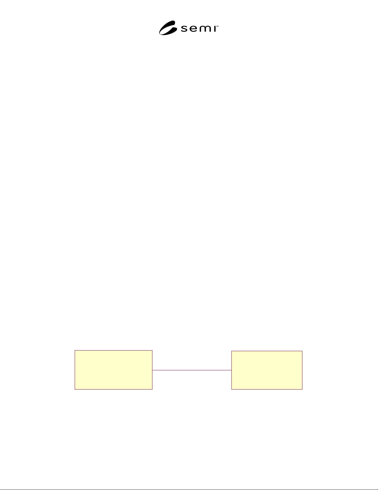
7.4.3.2.1 The Component Relationship Model was
developed specifically for the framework specification
as a mechanism to show relationships among
framework components. It shows the logical
combination of components and the relationships
among the component parts. Figure 22 depicts the
Component Relationship Model.
7.4.3.2.2 This model is based on the Unified Modeling
Language (UML) Class Diagram [UML] with added
stereotypes to represent the components. The UML
Association concept is abstracted to represent the high-
level relationships between components of the
framework.
7.4.3.3 Component Information Model
7.4.3.3.1 The Component Information Model shows
the specified CIM Framework interfaces along with the
relationships between those interfaces. This model is
based on the UML Class Diagram [UML] with the
stereotype «Interface» to indicate that the classes are
interfaces rather than implementation artifacts. This
model shows generalization as applied to interface
inheritance, aggregation of interfaces, and the use of an
Association Class to represent data associated with an
association between two interfaces. The associations
also capture specific semantics of the relationship,
including multiplicity and optionality as shown in
Figure 23.
B
<<Component>>
A
<<Component>>
Association
Figure 22
Component Relationship Model