semi合集-English.pdf - 第458页
SEMI E66-1103 © SEMI 1997, 2003 7 Figure 5 Particle Test Flow Chart

SEMI E66-1103 © SEMI 1997, 2003 6
9.1.2 Isokinetic Sampling — Isokinetic sampling is
used when the test flow is greater than the sample flow.
(See Figure 2.)
NOTE 1: An alternative size IKS may be substituted for the
IKS described in Sections 9.1.2.1 through 9.1.2.7 as long as it
collects a representative sample of particles that is not
influenced by flow characteristics and/or particle size.
9.1.2.1 Select the appropriate IKS (see Figure 3) from
Table 1 for the test flow. This is the smallest IKS that
exceeds the flow of the DUT.
9.1.2.2 The average velocity of the gas through the
sampling probe shall approximate the average velocity
in the tubing in which the sampling probe is inserted.
The sample flow used to calculate the sampling probe
diameter is the total flow drawn by the counter.
9.1.2.3 The tip of the sampling probe is to have a 30_
taper on the outside diameter.
9.1.2.4 The pick-off point is to be centered within the
flow stream.
9.1.2.5 The pick-off point is to be at a minimum
distance of 15 diameters of the primary flow tube
upstream or downstream from any connection.
9.1.2.6 Flow stability within the isokinetic sampler is
maintained by the bypass MFC.
9.1.2.7 To determine the dimensions of the isokinetic
sampler, as shown in Table 1, the following equations
and conditions are used:
10 Preparation of Apparatus
10.1 Setup and Schematic for Direct Sampling — See
Figure 1.
10.1.1 Install the spool piece between points A and B.
10.1.2 Set nominal supply pressure to 308.10 kPa (30
psig).
10.1.3 Cycle the supply MFC, switching between a low
flow and maximum purge flow as quickly as is
reasonably possible. Cycle every five seconds for at
least 30 minutes. The maximum purge flow should be
as high as possible and no less than twice the test rate.
During this initial cleanup, the particle counter should
be off-line.
10.1.4 Moisture from an inboard leak can cause
particle counts on some particle counters. Test the
system for leak integrity per SEMI F1 – Subsystems
Inboard Leak Test.
10.2 Setup and Schematic for Isokinetic Sampling —
See Figure 2.
10.2.1 Install the spool piece between points A and B.
10.2.2 Set nominal supply pressure to 308.10 kPa (30
psig).
10.2.3 Cycle the supply MFC, switching between a low
flow and maximum purge flow as quickly as is
reasonably possible. Cycle every five seconds for at
least 30 minutes. The maximum purge flow should be
as high as possible and no less than twice the test rate.
During this initial cleanup, the particle counter should
be off-line.
10.2.4 Moisture from an inboard leak can cause
particle counts on some particle counters. Test the
system for leak integrity per SEMI F1 – Subsystems
Inboard Leak Test.
10.3 Select the appropriate isokinetic sampler based on
the maximum test flow of the DUT, using Table 1 and
Figure 3. The size of the sampler should be equal to or
greater than the maximum test flow.
11 Calibration and Reference Standards
11.1 Calibrate instruments regularly according to the
manufacturer’s recommendations.
12 Test Procedure
The test apparatus is to be enclosed in a Class 100
environment (in accordance with ISO 14644). Test
must be performed in the sequence described below.
(See Figures 5 and 6.)
Measure DUT in purge mode to determine flow or use
the value supplied by the manufacturer. This will
determine which apparatus to use, direct sampling
(Figure 1) or IKS (Figure 2). Both of the test apparatus
may be required for testing a wide range of flow
controllers.
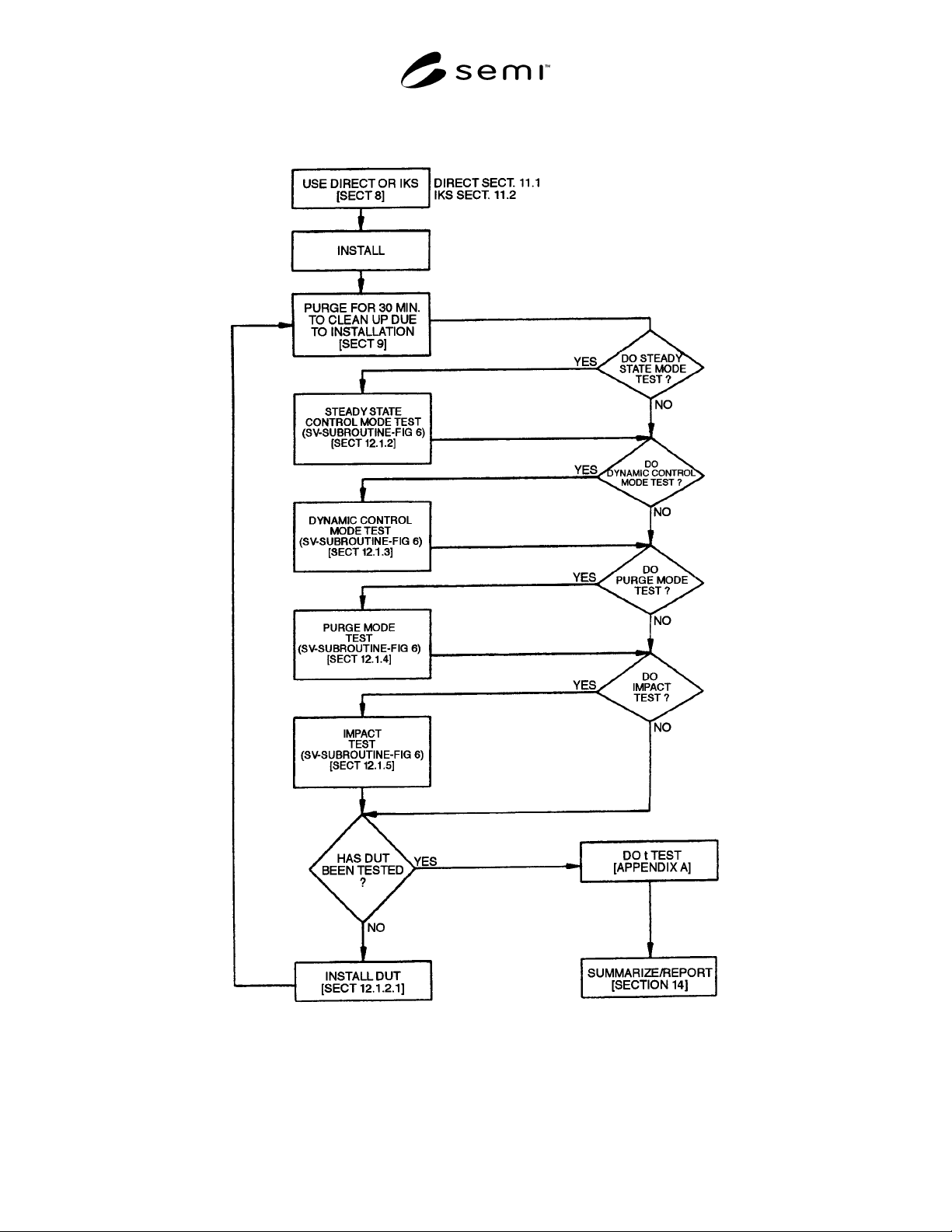
SEMI E66-1103 © SEMI 1997, 2003 7
Figure 5
Particle Test Flow Chart
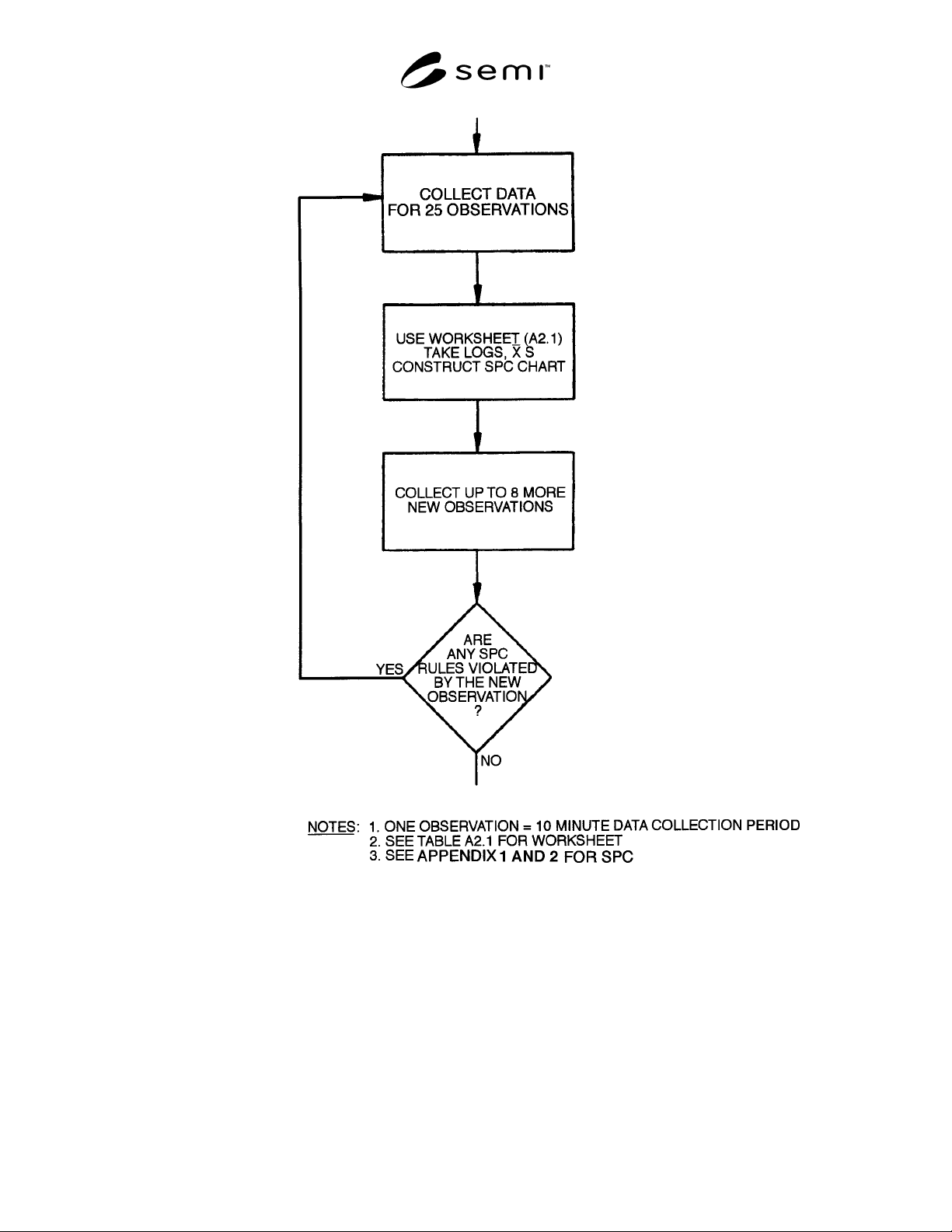
SEMI E66-1103 © SEMI 1997, 2003 8
Figure 6
Statistical Validity Subroutine
12.1 Procedure for Direct Sampling — See Figures 5
and 6.
12.1.1 Background Count Determination — Insert
spool piece between points A and B (see Figure 1).
12.1.2 Steady State Control Mode Background Test —
Set supply MFC (SFC) to the intended test flow value
of the DUT. For this test, the 100% full scale value is
recommended.
12.1.2.1 Count particles for the time necessary to
achieve a stable particle level.
12.1.3 Dynamic Control Mode Background Test —
Cycle the SFC from 10% to 100% of the DUT’s rated
flow. The cycle period is equal to two times the settling
time of the DUT with the longest settling time. (This
will ensure that all MFCs in a given test are tested at the
same cycle time.)