semi合集-English.pdf - 第200页
SEMI E25-92 © SEMI 1992, 2004 3 Figure 1 Figure 2 7 Related Documents 7.1 SEMI Docume nts SEMI E6 — SEMI Facilities Interface Specifications Guideline and Form at

SEMI E25-92 © SEMI 1992, 2004 2
4.3 Outboard Plane — The outboard surface should be
limited to non-rigid lines. To minimize potential
mechanical damage, chemical utilities should not enter
through the lower half of this surface.
4.4 Sides — In order to facilitate maintenance access,
utilities and facility services should not penetrate the
module envelope sides.
4.5 Top Surface — The top surface is preferred for
power, exhaust, process gases and make-up air.
Communications and electronic control harnesses could
also enter through this surface.
4.6 Bottom Surface — The bottom surface is preferred
for vacuum lines and all liquid supplies, returns and
drains. The location of all lines should not restrict the
removal of the module.
5 Module Considerations
5.1 The locations of utility and facility lines and
connections to the module, which is located within the
module envelope, are given below.
5.2 Exhaust, Vacuum and Make-up Air — The size of
piping for exhaust, vacuum and make-up air suggests
that the module sides are undesirable locations for
connections.
5.3 Maintenance Access — Utility and facility lines
and connections to the module sides should not com-
promise maintenance access to the module. Connect-
ions should be located above or below areas requiring
periodic maintenance access.
5.4 Liquids — Liquid supply connections to the
module sides should be as low as practical.
5.5 Electrical Components — Electrical components
that need to be accessible for maintenance while
energized should not be located at the sides of the
module. (See SEMI S2.)
5.6 Remote Equipment — For ease of maintenance
access, some pieces of equipment (for example, coolant
chiller and RF power supplies) may be located outside
the module envelope. In such cases, the lines and
connections between the remote equipment and the
module should follow this guideline.
6 Examples
6.1 The relationship between the location of specific
utility and facility lines entering the module envelope
and their subsequent routing and connection to the
module within the module envelope is illustrated by the
following examples.
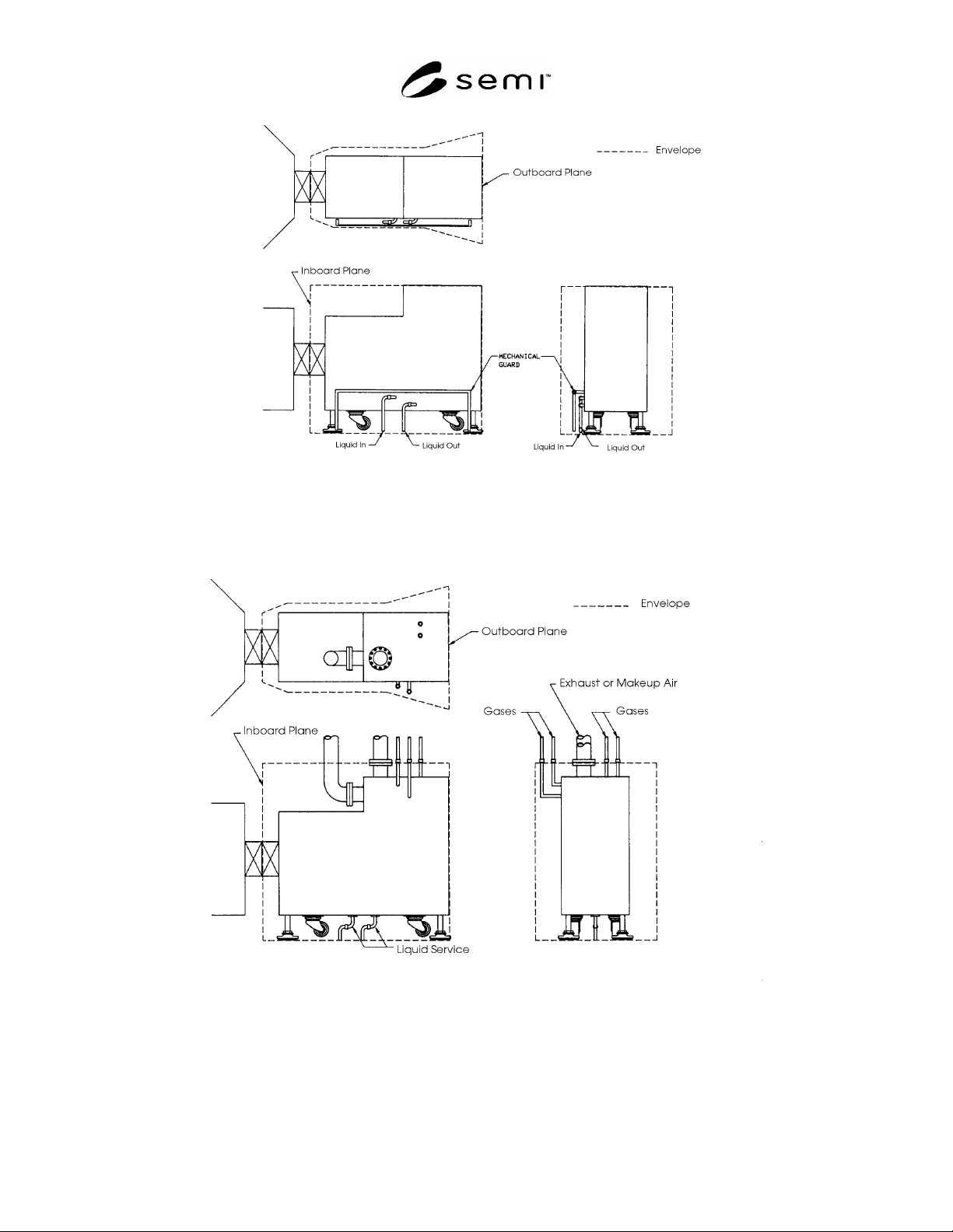
6.2 Liquid Connections — Two suggested methods of
providing liquid connections are shown in Figures 1
and 2. The liquid lines enter through the bottom of the
module envelope (see Section 4.5) then connect to
either the side of the module or the bottom of the
module (see Section 5.3).
6.3 Gas Connections — Two suggested methods of
providing gas connections are shown in Figure 2. The
gas lines pass through the top of the module envelope
(see Section 4.4), and then connect to the module either
at the top or at the side.
6.4 Exhaust and/or Make-Up Air — Two suggested
methods of providing exhaust and/or make-up air
connections are shown in Figure 2. The exhaust line
passes through the top of the module envelope (see
Section 4.4) and then connects to the module at or near
the top. Exhaust and make-up air connections are
flanged in Figure 2.
SEMI E25-92 © SEMI 1992, 2004 3
Figure 1
Figure 2
7 Related Documents
7.1 SEMI Documents
SEMI E6 — SEMI Facilities Interface Specifications
Guideline and Format

SEMI E25-92 © SEMI 1992, 2004 4
SEMI E26 — Radial Cluster Tool: Module Footprint
Standard.
NOTICE: SEMI makes no warranties or
representations as to the suitability of the guidelines set
forth herein for any particular application. The
determination of the suitability of the standard is solely
the responsibility of the user. Users are cautioned to
refer to manufacturer's instructions, product labels,
product data sheets, and other relevant literature,
respecting any materials or equipment mentioned
herein. These standards are subject to change without
notice.
By publication of this guideline, Semiconductor
Equipment and Materials International (SEMI) takes no
position respecting the validity of any patent rights or
copyrights asserted in connection with any item
mentioned in this guideline. Users of this guideline are
expressly advised that determination of any such patent
rights or copyrights, and the risk of infringement of
such rights are entirely their own responsibility.
Copyright by SEMI® (Semiconductor Equipment and Materials
International), 3081 Zanker Road, San Jose, CA 95134. Reproduction of
the contents in whole or in part is forbidden without express written
consent of SEMI.