semi合集-English.pdf - 第1990页
SEMI E54.5-0997 © SEMI 1997, 2004 6 Figure 5 Second and Third Levels of the SEMI Object Type Hierarchy The optional sensor and actuat or objects d escribed in the SEMI E54 specification may be instances of existing SDS o…
SEMI E54.5-0997 © SEMI 1997, 2004 5
7.1 Embedded Object Type Hierarchy — SDS
classifies Embedded Objects into specific object types
(classes), and these types are organized into a class
inheritance hierarchy. (For more information on
classification and inheritance, see SEMI E39 -- Object
Services Standard). Each SDS object type specifies the
details of an object’s attributes, actions, and events. The
Embedded Object (an instance of a type) is a network-
addressable entity within a logical device. The
classification identifies common characteristics and
enables reuse of object definitions. The top two levels
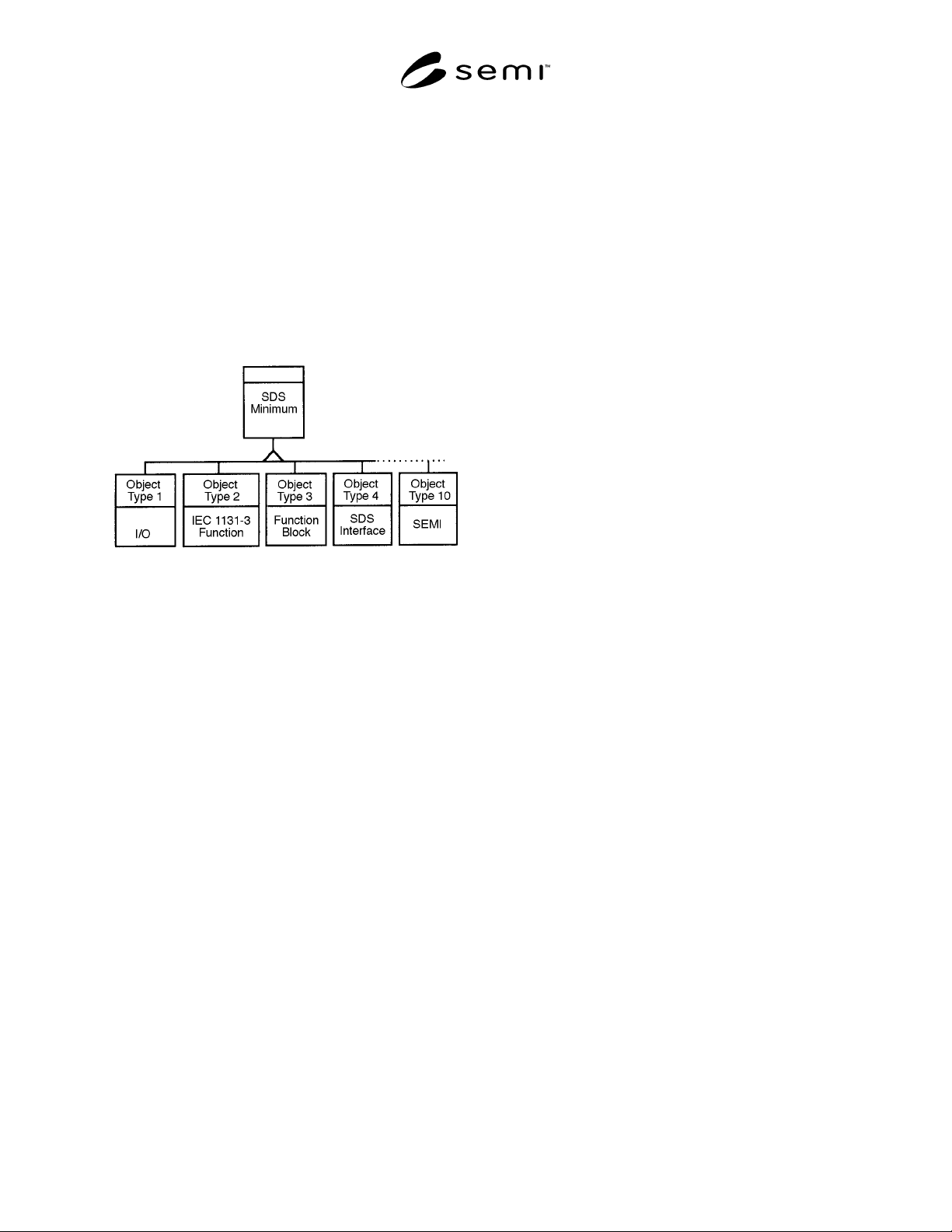
of that hierarchy are shown in Figure 4 below.
Figure 4
Top Levels of the SDS Embedded Object Type
Hierarchy
The SDS object types are specified in detail in the SDS
Component Modeling Specification. There are four
primary Embedded Object types in the SDS type
hierarchy. These include: I/O, IEC 1131-3 Function
Object, Function Block, and SDS Interface. In addition,
a new SEMI object type has been defined for use in
developing classes necessary for SEMI SAN-compliant
networks. Each of these object types is derived from a
common type called SDS Minimum, which defines the
minimum characteristics that are common to all SDS
Embedded Objects.
All SDS object types inherit from the SDS Minimum
object type, which provides the fundamental
characteristics of an SDS device. The other top level
SDS object types shown in Figure 4 are summarized
below.
I/O Object (Type 1) — Defines the general
characteristics of objects used for process I/O type
functions. Subtypes of this type specify input and
output objects with either analog or digital process
variables. These may be used in SAN devices as the
sensor or actuator objects.
IEC 1131-3 Function Object (Type 2) — Defines
standard IEC 1131-3 Function Objects such as counters,
timers, type conversion, bit-wise operations, character
strings, etc.
Function Block Object (Type 3) — Collections of
function objects that have a specific set of inputs and
outputs (e.g., a predefined control algorithm). These
may be used in the SAN devices as the controller
objects.
SDS Interface Object (Type 4) — Models, network
interfaces, gateways, etc.
SEMI Object (object Type 10) — Implement the
additional object types necessary for SEMI SAN-
compliant networks.
7.1.1 SEMI Objects — To implement SEMI-specific
object types, the SDS object type hierarchy is
augmented with type number 10 - SEMI object. This
type, and the types derived from it, specify the new
functionality necessary to implement this SEMI
standard. Object type 10 is defined to include the
common required attributes, services, and behaviors as
described in the SAN Common Device Model standard
SEMI E54. This definition is in terms of SDS
Attributes, Actions, and Events.
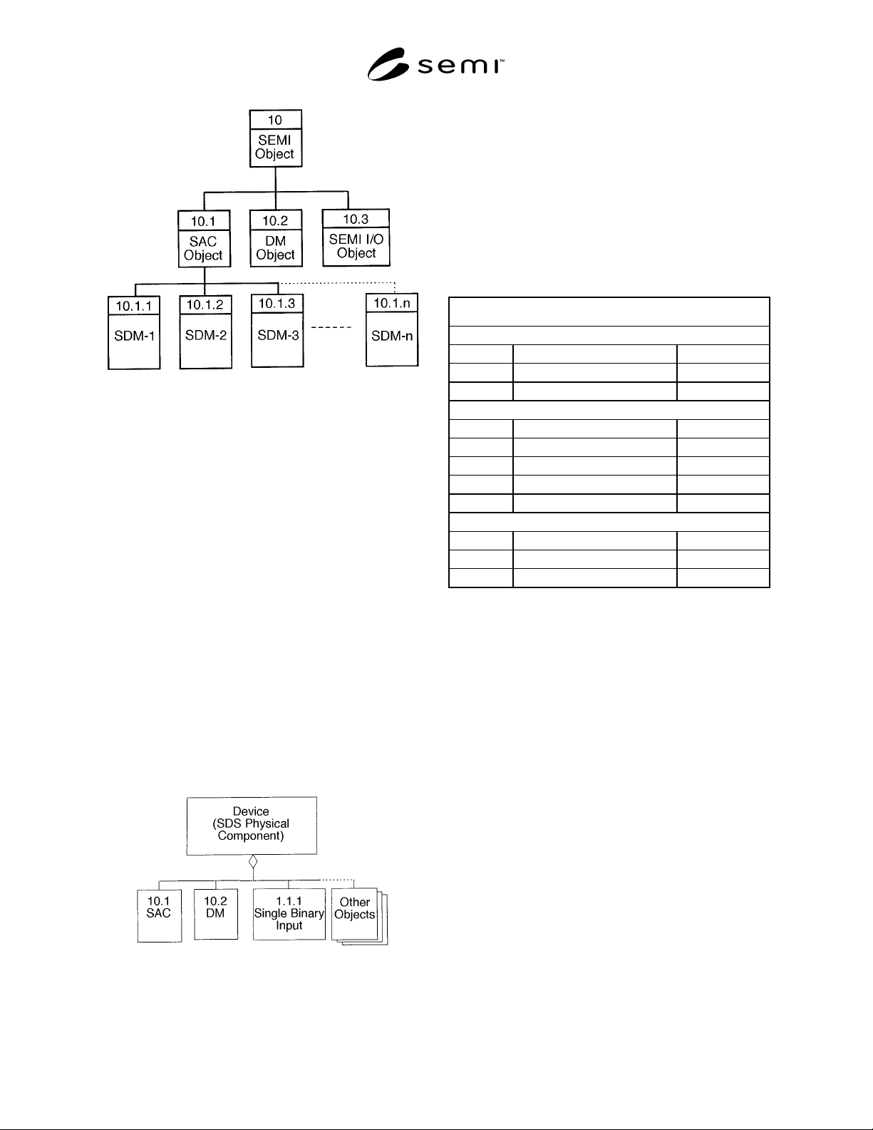
In addition, there are derived types: types 10.1
implementing the SAC object and 10.2 implementing
the Device Manager (DM) object (Figure 5). Object
instances of these types are required in the Common
Device Model document SEMI E54.
Each object type inheriting from the SEMI Object type
10 (e.g., 10.1 SAC object) automatically includes the
features of the SEMI Object. Thus, both the SAC and
the DM object have the reset, abort, and recover actions
that are defined for the SEMI Object type 10. (See
Section 7.2.) The Device Manager type augments the
SEMI Object to provide the required characteristics
over and above those specified in type 10 and SDS
minimum.
As specific device models are defined, the SAC object
type will be refined to be specific to that device. These
object types are indicated in Figure 5 as object types
SDM-1, SDM-2, etc. (examples include: Mass Flow
Controller, Particle Counter, and Capacitance
Manometer SAC objects). These object types have (at
least) the set of attributes, actions, and events inherited
from SDS Minimum, the SEMI Object type, and the
SAC object type. Additionally, each SDM-n may have
other, unique attributes, actions, and events which
implement the desired behavior of a specific device
SAC object.
SEMI E54.5-0997 © SEMI 1997, 2004 6
Figure 5
Second and Third Levels of the SEMI Object Type
Hierarchy
The optional sensor and actuator objects described in
the SEMI E54 specification may be instances of
existing SDS object types (e.g., of type I/O object in
Figure 4). In cases where a desired object type is not
available under SDS object type 1, new I/O object types
may be defined as sub-types of object type 10.3 SEMI
I/O object.
7.1.2 Example SEMI Device — For clarification
purposes, an example SEMI device is shown in Figure
6 (using Rumbaugh notation). It consists of three (or
more) objects, including a DM, SAC, and binary input
object. This is a complete and fully functional SEMI
SAN-compliant digital input device.
In Figure 6, the Device is assigned an SDS address
(e.g., 125), and each object is assigned an object
instance number. The device address may be changed
during installation. Each SDS message contains a
device address and an object instance number.
Figure 6
Example Device with Multiple Objects
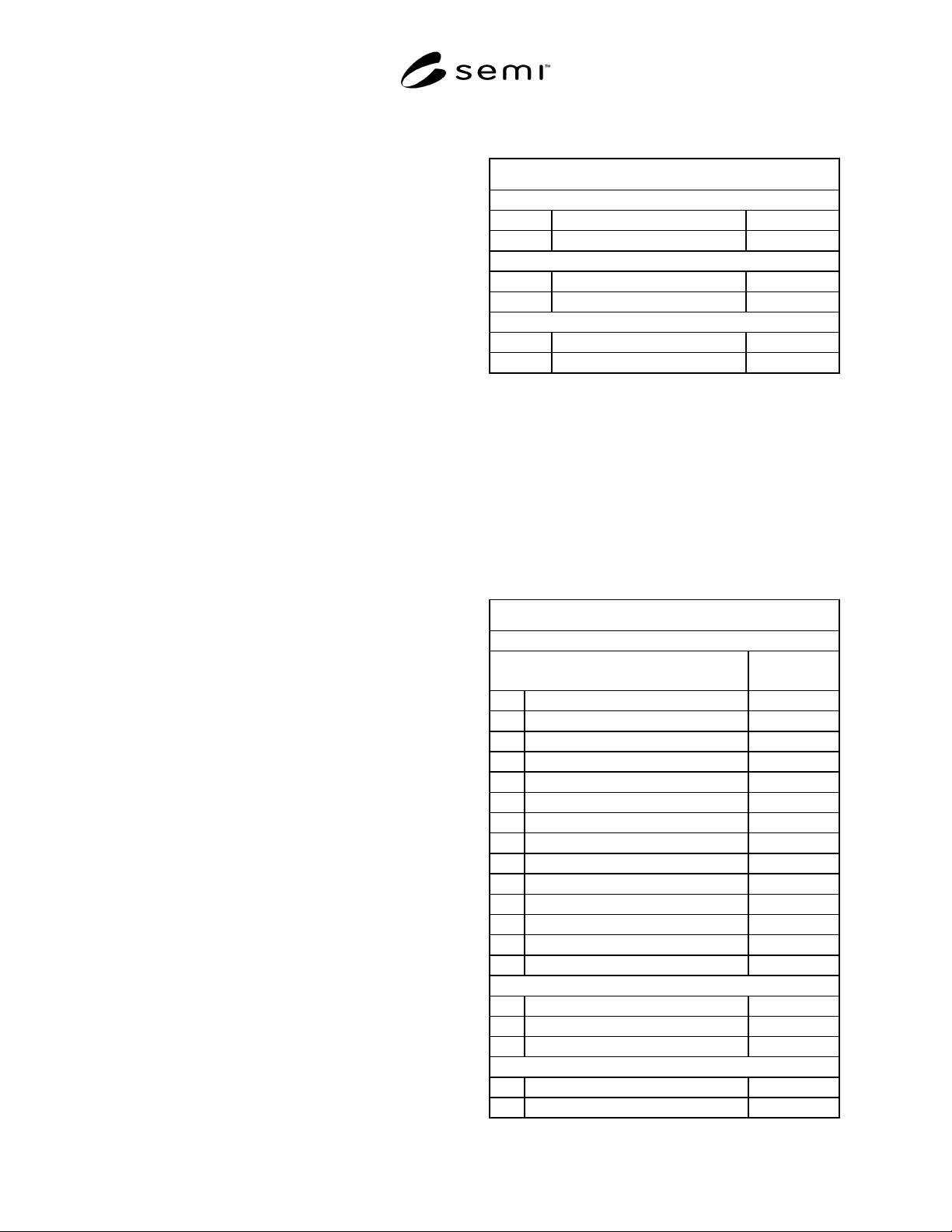
7.2 SEMI Object Type 10 Definition — Table 2
formally specifies the SEMI Object (type 10). The three
sections in this table specify SDS identifiers to code the
required attributes, actions, or events. The first column
is the SDS identifier number, the unique identifier used
in SDS messaging. The second column is the SEMI
E54-specified name associated with the ID#. The third
column identifies the associated tag name (identifier)
used in SEMI E54.
Table 2 Table 2 SEMI Object Common Level
Model(Object Type 10)
Type 10 SEMI Object Common Structure and Behavior
Attributes
ID Name SEMI E54 tag
None defined.
80–144 SEMI Reserved Attribute IDs Reserve
Actions
ID Name SEMI E54 tag
80 Reset SacS1/DmS1
81 Abort SacS2/DmS1
82 Recover SacS3/DmS3
83–95 SEMI Reserved Action IDs Reserve
Events
ID Name SEMI E54 tag
None defined.
80–95 SEMI Reserved Event IDs Reserve
There are no attributes that are currently identified in
SEMI E54 that are common to all SEMI objects. As a
result, there are no attributes defined in the table.
However, 64 attribute IDs have been reserved for use in
other sub-types derived from type 10 in this document
and in future revisions of this document.
SEMI E54 defines three service requests (reset, abort,
and recover) that are common to the Device Manager
and the SAC objects. These service requests are
implemented as specific SDS Actions. Each service is
mapped to a designated SDS action in Table 2. The
actions are identified as ID# 80, 81, and 82
respectively. Additional action identifiers are reserved
for use in sub-types of this type and for future use.
Not explicitly shown as Actions are the SEMI E54 Get
and Set Attribute services. The equivalent behavior is
provided by the SDS Read and Write Attribute services
that are implicit for every attribute.
The execution of a service request may cause a change
in the object’s state variable. When a device receives an
SDS action message indicating a service request, the
object transitions to the appropriate state, after which an
SDS response message is transmitted to the service
SEMI E54.5-0997 © SEMI 1997, 2004 7
requester indicating the response to the request. For
example, the SAC Object Instance Behavior State
Transition Matrix in Table 4 of the SEMI E54
document defines the valid SAC state transitions.
Service Notifications (as defined in SEMI E54) are
implemented with specific SDS event messages which
are specified in the third part of the table. The SEMI
object (type 10) has no events defined at this time.
Additional event identifiers are reserved for use in sub-
types of this type and for future use.
7.3 Implementation of Sensor/Actuator/Controller
Object Type (SAC) — A single instance of a SAC
object type is required in each SAN device. The actual
object type used will typically be derived from the SAC
object type rather than this exact type. The derived type
will have added services and attributes that are device-
specific (according to a Specific Device Model
specification). The generic SAC type is, nevertheless,
defined as a semantic type definition (sensor actuator
controller object). The features of the SAC object
include service requests (for Reset, Abort, Recover,
etc.) that are mapped to SDS Action functions. Since
these have been defined in the super type (object type
10), they are not re-defined here.
7.3.1 SDS Object Model for Sensor/Actuator/Control-
ler Object Type (SAC) — The SDS object model for the
SAC object type (Table 3) needs only to include the
appropriate mapping for SAC-specific attributes and
behavior (i.e., augmenting the SEMI Object Common
Level - Table 8-1). The SAC Object Model contains no
attributes, actions, or events beyond those specified in
its super type (type 10).
An implementor of a specific device will normally
derive a new SAC object type and add new attributes,
actions, or events as necessary (i.e., 10.1.1 MFC SAC
Object). Object type 10.1 is, in essence, a semantic
grouping only—for a group of device-specific SAC
object types implementing specific behavior.
The default object identifier that should be used for the
SAC object in an SDS device is 1. The actual object
identifier used may be reassigned by the implementor.
The identifier may be determined on line via reading
the object type attributes from all objects on the device.
Table 3 Table 3 SAC Object Model (Object Type
10.1)
Type 10.1 Sensor/Actuator/Controller Object Model
Attributes
ID Name SEMI E54 tag
None defined.
Actions
ID Name SEMI E54 tag
None defined.
Events
ID Name SEMI E54 tag
None defined.
7.4 Implementation of Device Manager Object Type
(DM) — A single instance of this type is required on
each device.
7.4.1 SDS Object Model for Device Manager Object
Type (DM) — The SDS object model for the DM object
type includes the appropriate mapping for DM-specific
attributes and behavior to SDS-specific identifiers
(Table 4).
Table 4 Table 4 DM Object Model (Object Type
10.2)
Type 10.2 Device Manager (DM) Object Model
Attributes
ID
Name
SEMI E54 tag
81 Device Type DmA1
82 Standard Revision Level DmA2
83 Device Manufacturer Identifier DmA3
84 Manufacturer Model Number DmA4
85 Software or Firmware Revision Level DmA5
86 Hardware Revision Level DmA6
87 Serial Number (optional) DmA7
88 Device Configuration (optional) DmA8
89 Device Status DmA9
90 Reporting Mode DmA10
91 Exception Status Timer (optional) DmA11
92 Exception Status DmA12
93 Exception Detail Alarm (optional) DmA13
94 Exception Detail Warning (optional) DmA14
Actions
ID Name SEMI E54 tag
83 Execute DmS6
84 PerformDiagnostics DmS7
Events
ID Name SEMI E54 tag
81 Publish Attribute DmS8