semi合集-English.pdf - 第3885页
SEMI F26-0697 © SEMI 1997, 2003 5 NOTICE: SEMI makes no warranties or representations as to the suitability o f the standards set forth herei n for any particul ar applicat ion. The determination of the suitability of th…
SEMI F26-0697 © SEMI 1997, 2003 4
RELATED INFORMATION 1
NOTES ON ASPIRATION EFFICIENCIES OF WALL TAP SAMPLE
PORTS
NOTICE: This related information is not an official part of SEMI F26 and is not intended to modify or supercede the official
standard. Determination of the suitability of the material is solely the responsibility of the user.
R1-1 Introduction
R1-1.1 Isokinetic sample probes are usually not
provided in speciality gas systems. Particle sampling is
usually performed using wall tap sample ports. Wall
tap sample ports are oriented 90° to the process line
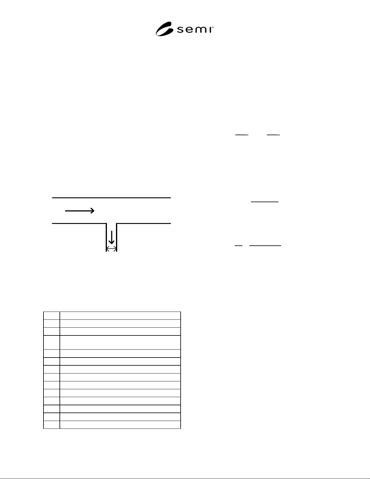
flow as shown in Figure R1-1. Non-isokinetic flow into
the sample tube results from the 90° change in flow
direction. Additional deviation from isokinesis can
result from stream tube contraction or expansion when
the velocities U and v are not equal. The effects of
non-isokinetic flow on the measurement should be
checked. The particle sampling process should be
performed with an aspiration efficiency close to 1.
Process Line
v, C
To Sampling System
Wall Tap
D
U, Co, p
Figure R1-1
Schematic Diagram of Process Line and Wall
Tap Sample Port
R1-2 Variables
d
p
= Diameter of particle (cm)
ρ
p
= Intrinsic density of particle (g/cm
3
)
η = Dynamic viscosity of the gas (g/s-cm)
λo = Mean free path of the gas at atmospheric pressure
(cm)
p = Pressure of the gas (Pa)
P
O
= Atmospheric pressure (= 1 × 10
5
Pa)
D = Diameter of wall tap sample tube (cm)
U = Average velocity of the process line flow (cm/s)
v = Average velocity of the sample line flow (cm/s)
C* = Stokes-Cunningham slip correction factor
S
tk
= Stokes number
R = Velocity ratio
Co = Particle concentration in the process line (cm
–3
)
C = Particle concentration in the sample line (cm
–3
)
R1-3 Calculations
R1-3.1 The Stokes-Cunningham slip correction factor
is calculated for particles in the size range of interest:
C* = 1 + 2.492
p
o
λ
o
pd
p
+
0.84
p
o
λ
o
pd
p
e
−
0.435pd
p
/p
o
λ
o
Calculate the velocity ratio and Stokes number. The
intrinsic particle density may assume a worst case value
of 10 g/cm
3
:
R
=U/v
S
tk
=
d
p
2
ρ
p
UC*
18
η
D
A wall tap sample port can be approximated as a
sampling probe oriented 90° to the flow. Calculate the
aspiration efficiency:
C
Co
=
1
1 + 8S
tk
R
1/2
Repeat the calculations for particle sizes in the range of
interest. When the aspiration efficiency is significantly
different from 1, the calculated efficiency should be
used to correct the measured particle concentration, C.
R1-4 References
Stevens, D. C. Review of Aspiration Coefficients of
Thin-Walled Sampling Nozzles. J. Aerosol Sci.,
17(4):729-743, 1986.
Vincent, J. H., D. C. Stevens, D. Mark, M. Marshall,
and T. A. Smith. On the Aspiration Characteristics of
Large-Diameter, Thin-Walled Aerosol Sampling Probes
at Yaw Orientations With Respect to the Wind. J.
Aerosol Sci., 17(2):211-224, 1986.

SEMI F26-0697 © SEMI 1997, 2003 5
NOTICE: SEMI makes no warranties or
representations as to the suitability of the standards set
forth herein for any particular application. The
determination of the suitability of the standard is solely
the responsibility of the user. Users are cautioned to
refer to manufacturer's instructions, product labels,
product data sheets, and other relevant literature,
respecting any materials or equipment mentioned
herein. These standards are subject to change without
notice.
By publication of this standard, Semiconductor
Equipment and Materials International (SEMI) takes no
position respecting the validity of any patent rights or
copyrights asserted in connection with any items
mentioned in this standard. Users of this standard are
expressly advised that determination of any such patent
rights or copyrights, and the risk of infringement of
such rights are entirely their own responsibility.
Copyright by SEMI® (Semiconductor Equipment and Materials
International), 3081 Zanker Road, San Jose, CA 95134. Reproduction o
f
the contents in whole or in part is forbidden without express written
consent of SEMI.

SEMI F27-0997 © SEMI 1997, 2003 1
SEMI F27-0997 (Reapproved 1103)
TEST METHOD FOR MOISTURE INTERACTION AND CONTENT OF
GAS DISTRIBUTION SYSTEMS AND COMPONENTS BY
ATMOSPHERIC PRESSURE IONIZATION MASS SPECTROMETRY
(APIMS)
This test method was technically reapproved by the Global Gases Committee and is the direct responsibility
of the North American Gases Committee. Current edition approved by the North American Regional
Standards Committee on September 16, 2003. Initially available at www.semi.org October 2003; to be
published November 2003. Originally published September 1997.
1 Purpose
1.1 This test will determine the quantity of removable
moisture and the degree of interaction with trace
concentrations of gas phase moisture, of gas
distribution systems and components. APIMS is
currently the technique of choice for such tests because
it is essentially the only commercially available method
capable of ppt moisture analysis and because of its
superior response time. This method may provide
guidelines for the application of other techniques with
similar detection limits and response time to APIMS
which are not commercially available at this time.
1.2 The results of this test can be used for qualitative
ranking of systems and components and can also be
used, by a sufficiently sophisticated user, as input for
numerical simulation of distribution system behavior.
2 Scope
2.1 System and Component Types — This procedure
applies to in-line components to be used to contain
electronics grade materials in semiconductor gas
distribution systems. The following components are
expected to yield meaningful results when tested
according to the present method: tubing, connectors
(fittings), particle filters, valves (check, relief, shut-off,
and metering), regulators, flow-through
transducers/sensors, mass flow controllers and meters.
Components with dead volumes, such as pressure
gauges, can be tested according to this method, but the
results will be difficult to interpret. Additional criteria
besides those considered here need to be developed for
testing components with dead volumes.
2.1.1 As gas phase moisture levels are dominated by
desorption from surfaces, the procedure is expected to
be most useful for components of large surface area
such as particle filters and tubing. Components with
very small wetted surface areas may have moisture
interactions which are too small to measure using this
test. Check valves and relief valves can be tested only if
their operating parameters are consistent with the test
conditions.
2.1.2 Tubing samples must be rather long (3–4 m) to
yield useful results, but they can be bent into a U shape
in order to be accommodated into a practical test bench.
Radii of curvature should be no less than 6 times the
internal diameter of the tube and the minimum number
of bends should be used. Most ultra-high purity
components are currently supplied with metal gasket
connectors, so the test bench employed should be fitted
with mating connectors. This type of fitting is usually
welded to tubing, which is not recommended as it
introduces a potential source of uncontrolled variability
to the experiments. Instead, a compression fitting on the
tube and a suitable adapter should be used. The
compression fitting should not be disconnected after
initial connection until the test series is over. In this
way, deterioration in integrity of the connection can be
avoided. The same type of gasket to compression fitting
adapter should be used for all tubing samples.
2.1.3 Purifiers require special test procedures and are
not addressed here.
2.1.4 Simple systems consisting of components
connected in line can be tested by the present method.
Complex systems (i.e., those with more than one
potential inlet and/or outlet) will show performance
which varies depending on the test configuration
(which inlets and outlets are chosen). Testing of such
systems is not addressed by the current document.
2.2 Gases — The procedure will be carried out in
nitrogen. The results will provide a ranking with respect
to moisture contribution which may be applied with due
caution to components intended for use in other gas
streams. Other “inert” gases will have different purging
characteristics and may dry a component more quickly
or slowly. Reactive gases may react chemically with
moisture. Considerations relating to corrosion
resistance are outside the scope of the present
document, although the test procedure may prove useful
in corrosion studies.
2.3 Operating Situations — Moisture contribution from
a component may be the result of contamination arising
in its manufacture, or from subsequent exposure to