semi合集-English.pdf - 第6291页
SEMI G58-94 © SEMI 1994 6 10 Packaging and M arking 10.1 Packagi ng — The sh ipping co n t ai ners and materials shall be suitability desig ned to provide the compon e nts with protection ag ainst normal transp ort ation…

SEMI G58-94 © SEMI 19945
8.1.3.3 External Lead Plating (if applicable)
8.1.3.3.1 Thickness — Shall be measured by X-ray
fluorescence.
8.1.3.3.2 Solderability — Shall be tested per MIL-
STD-883, Method 2003.
8.2 Functional Testing
NOTE 6: All procedures used to functionally test the
components shall be agreed between user and supplier.
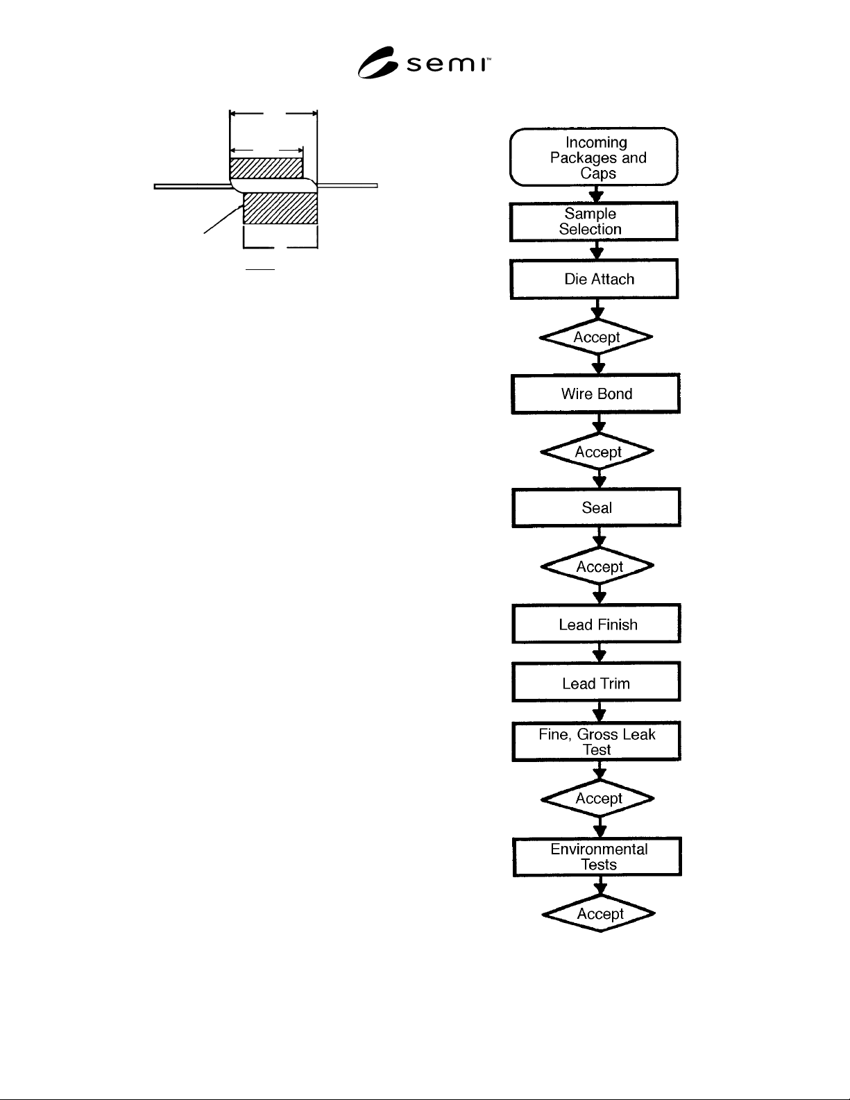
The sequence of functional testing shall be as shown in
Figure 8.
8.2.1 Die Attach
8.2.1.1 Visual Inspection
Eutectic Bonding — Visually inspect the alloy wet-out
after die attach. The minimum wet-out requirement
shall be 100% of the die perimeter.
Silver Glass, Epoxy, or Polyimide Bonding — 100% die
perimeter coverage shall be required.
NOTE 7: 100% coverage for resin bonding is not a function
of package acceptability but is required to standardize die
shear testing. The inability of the resins to wet the surface of
the die attach area due to contamination is cause for rejection.
8.2.1.2 Die Shear Test — Perform destructive testing
per MIL-STD-883, Method 2019.
NOTE 8: This test may also be performed after environmental
testing. In the case of very large die, this test may not be
appropriate to fully evaluate the package. In these cases, die
sizes, agreed between vendor and customer, shall be used.
Alternatively, die pull testing may be used by agreement
between vendor and customer.
8.2.1.3 Radiographic Inspection for Voids — Perform
inspection per MIL-STD-883, Method 2012.
8.2.1.4 Ultrasonic Inspection for Voids, Delamination,
and Cracks — Perform inspection per MIL-STD-883,
Method 2030.
8.2.2 Wire Bond — On wire bonds that meet the
requirements of MIL-STD-883, Method 2010, perform
destructive testing per MIL- STD-883, Method 2011,
Test Condition D. Bonds which cause lifted
metallization from the leadframe fingers shall also be
cause for component rejection.
NOTE 9: This test shall be performed at pre-seal and post-
seal.
8.2.3 Seal
8.2.3.1 Visual Inspection — The glass sealant
appearance and flow shall be visually inspected for
conformance to agreed process criteria.
8.2.3.2 Cap Torque Test — This test shall be
performed per process agreement.
8.2.4 Lead Finish — Type A per MIL-M-38510 if
required.
8.2.5 Hermeticity — This test shall be performed per
MIL-STD-883, Method 1014, Test Condition A or B
and C. The package must maintain hermetic integrity
after each environmental test or sequence of tests.
8.2.6 Environmental Testing — Environmental
evaluation shall include, but not be limited to, the
following tests:
NOTE 10: The sequence of testing and the sample sizes for
each sub-group shall be agreed between vendor and customer.
8.2.6.1 Temperature Cycle — Per MIL-STD-883,
Method 1010, Condition C.
8.2.6.2 Thermal Shock — Per MIL-STD-883, Method
1011, Condition B.
8.2.6.3 Vibration Fatigue — Per MIL-STD-883,
Method 2005, Test Condition B.
8.2.6.4 Mechanical Shock — Per MIL-STD-883,
Method 2002, Test Condition B.
8.2.6.5 Constant Acceleration — Per MIL-STD-883,
Method 2001, Test Condition D, “Y” axis only.
8.2.6.6 Moisture Resistance — Per MIL-STD-883,
Method 1004.
8.2.6.7 Additional Testing — Additional tests
performed at package qualification may include
evaluation of electrical and thermal characteristics.
These tests may be performed on a periodic basis to
maintain package qualification.
These tests may include, but are not limited to, the
following:
8.2.6.7.1 Insulation Resistance — Per MIL-STD-883,
Method 1003, Test Condition as agreed between user
and supplier.
8.2.6.7.2 Lead Inductance — Per SEMI Test Method
G23.
8.2.6.7.3 Lead-to-Lead Capacitance — Per SEMI Test
Method G24.
8.2.6.7.4 Lead Resistance — Per SEMI G25.
8.2.6.7.5 Thermal Dissipation — Per MIL-STD-883,
Method 1012.
9 Sampling
The sampling plan, based on MIL-STD-105, shall be
agreed between user and supplier.
SEMI G58-94 © SEMI 1994 6
10 Packaging and Marking
10.1 Packaging — The shipping containers and
materials shall be suitability designed to provide the
components with protection against normal
transportation damage risks which include crushing and
spillage, and exposure to moisture and other corrosive
gases.
The packing materials must not cause particulate
contamination on the components.
10.2 Marking — The shipping container shall be
clearly marked with the following information:
Customer’s Part Number
Customer’s Purchase Order Number
Drawing Number (Customer’s and Vendor’s, if
appropriate)
Quantity
Vendor Lot Number
Shipping date
Figure 1
Chip Illustration
.010
.010
.015
.015
Figure 2
Critical and Non-Critical Seal Areas
overhang
overhang
rundown
external
pullback
window
frame
base
rundown
material
pullback
Figure 3
Glass Misalignment
.005
.015
75%
Figure 4
lead tip
overhang
lead
glass
ceramic base
Figure 5
A
B
L/F
cavity
A-B
2
Š .010 inch
Figure 6
SEMI G58-94 © SEMI 19947
ENV
S
window frame
base
L
ENV – L + Š .015
L – S
2
Figure 7
Figure 8