semi合集-English.pdf - 第2229页
SEMI E58-0703 © SEMI 1997, 2003 10 SEMI E10 Equipment States in Harel Notati on 8.2.2.1 TOTAL TIME — The TOTAL TIME state includes 100% of real time; th e sum of the time in the six basic SEMI E10 states, incl uding time…
SEMI E58-0703 © SEMI 1997, 2003 9
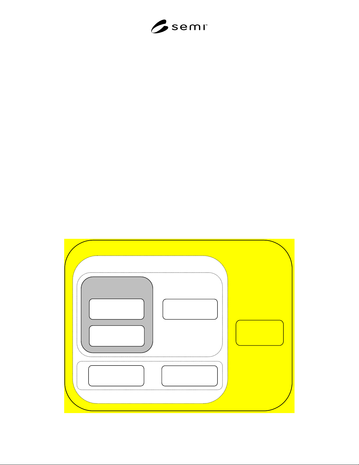
8.1 SEMI E10 Equipment States — Figure 1 contains a
diagram of SEMI E10 equipment states using the Harel
notation. SEMI E10 divides total time into six basic
states: PRODUCTIVE, ENGINEERING, STANDBY,
SCHEDULED DOWNTIME, UNSCHEDULED
DOWNTIME, and NON-SCHEDULED TIME. These
six states are shown in Figure 1 with solid lines.
1.14.3 OPERATIONS TIME, UPTIME,
DOWNTIME, and MANUFACTURING TIME are
derived by grouping states defined in SEMI E10 and
are useful for classification purposes, but formally they
are not considered as SEMI E10 equipment states. Time
in these groupings can be derived by summing the time
in their corresponding states, based on Figure 1.
NOTE 7: Figure 1 uses shadings to show derived states. It is
not intended as a formal state model.
1.14.4 MANUFACTURING TIME includes time
spent in PRODUCTIVE and STANDBY. UPTIME
includes the time spent in MANUFACTURING TIME
and ENGINEERING. DOWNTIME includes the time
spent in SCHEDULED DOWNTIME and
UNSCHEDULED DOWNTIME.
1.14.5 In SEMI E10, precise rules governing state
transitions are not required. The ARAMS model, in
contrast, is intended to be used by automated equipment
capable of detecting internal conditions. Conditions for
each valid state transition are defined, both those
initiated by equipment and those determined by
interactions between the user and the equipment.
8.2 ARAMS State Model Definition — This section
contains the formal definition of the ARAMS State
Model, consisting of three parts:
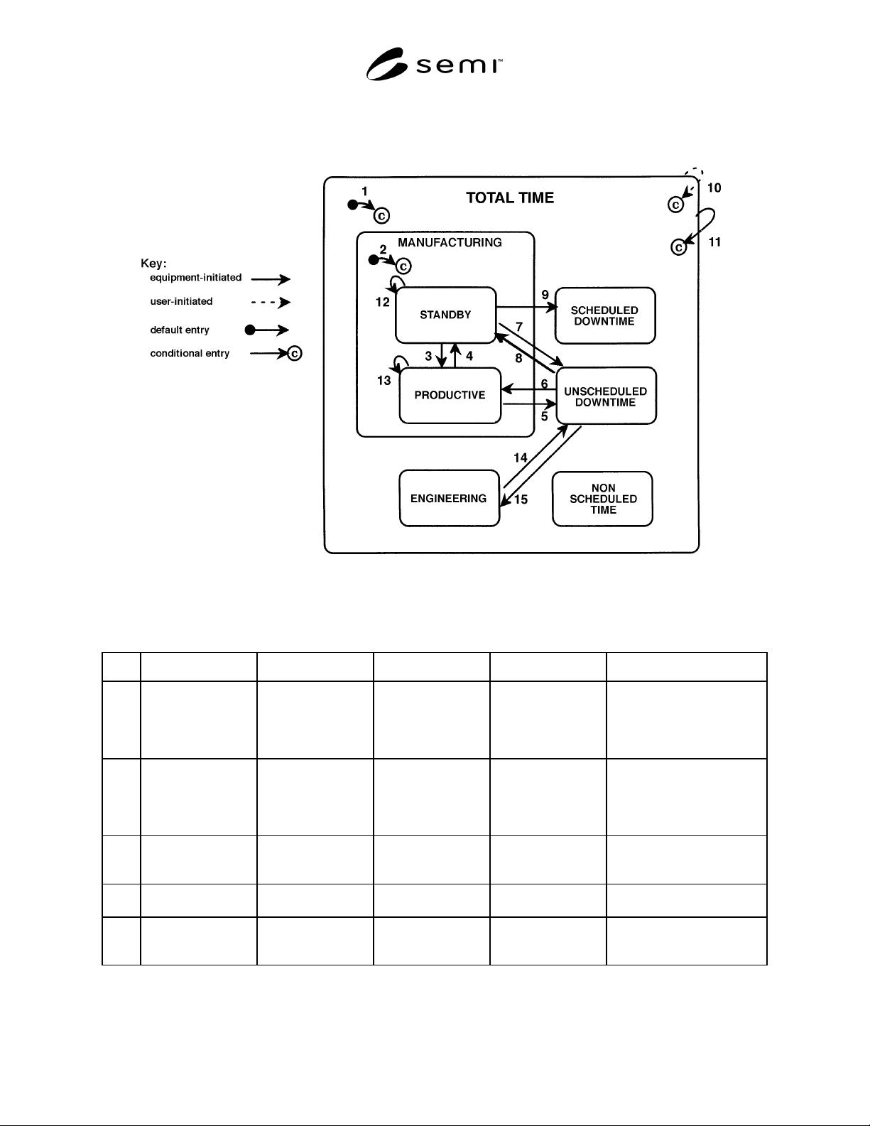
• A diagram of the ARAMS State Model (Figure 2),
using Harel notation,
• a description of each state and the behavior of the
equipment within that state, and
• a table of transitions (Table 1) showing the
previous state before the transition, the trigger for
the transition, the new state after the transition, a
description of any actions to be taken upon entry,
and comments concerning the new state.
8.2.1 ARAMS State Model Diagram — Figure 2
contains the diagram of the ARAMS State Model.
8.2.2 Descriptions of ARAMS States — This section
provides brief descriptions of the basic states for model
completeness.
NOTE 8: These are informal descriptions included for the
completeness of the ARAMS State Model. They do not
replace the formal definitions in SEMI E10.
TOTAL TIME
OPERATIONS TIME
NON-
SCHEDULED
TIME
STANDBY
PRODUCTIVE
MANUFACTURING
TIME
UPTIME
ENGINEERING
SCHEDULED
DOWNTIME
UNSCHEDULED
DOWNTIME
Figure 1
SEMI E58-0703 © SEMI 1997, 2003
10
SEMI E10 Equipment States in Harel Notation
8.2.2.1 TOTAL TIME — The TOTAL TIME state
includes 100% of real time; the sum of the time in the
six basic SEMI E10 states, including time when the
equipment is powered down. PRODUCTIVE,
STANDBY, and ENGINEERING are called uptime,
and SCHEDULED DOWNTIME and
UNSCHEDULED DOWNTIME are called downtime.
8.2.2.2 MANUFACTURING — The ARAMS State
Model includes MANUFACTURING as a user-
selectable superstate of PRODUCTIVE and STAND-
BY. When the user selects MANUFACTURING, the
equipment automatically transitions to either
PRODUCTIVE or STANDBY, depending upon its
internal status at the time.
1.14.5.1.1 Equipment is fault-free during
MANUFACTURING.
NOTE 9: MANUFACTURING is not a SEMI E10
equipment state.
8.2.2.3 PRODUCTIVE — The PRODUCTIVE state
covers the time spent by the equipment in performing
its intended function. This also includes time spent
loading and unloading product. PRODUCTIVE is an
uptime manufacturing state.
1.14.5.1.2 The equipment is in PRODUCTIVE when,
and only when, it is in MANUFACTURING, its
equipment production criteria are satisfied, and it is
busy performing its intended function.
NOTE 10: Although by definition, the equipment is only
considered to be “performing its intended function” in the
PRODUCTIVE state, equipment processing cycles may occur
in any of the basic SEMI E10 states except STANDBY.
8.2.2.4 STANDBY — The STANDBY state is an
uptime manufacturing state that covers the time the
equipment is waiting to enter the PRODUCTIVE state.
1.14.5.1.3 The equipment enters this state
automatically from the PRODUCTIVE state whenever
it is in the MANUFACTURING superstate and the
requirements for PRODUCTIVE do not apply. This
includes periods during which it detects a normal
standby condition, such as no work, no operator, etc.
During STANDBY, the equipment monitors conditions
for PRODUCTIVE. When all requirements for
PRODUCTIVE are satisfied, then it transitions
automatically to PRODUCTIVE.
8.2.2.5 ENGINEERING — The ENGINEERING state
is an uptime state that is selected by the user for process
and equipment engineering purposes, such as process
development or characterization.
1.14.5.1.4 Because the equipment may be pushed
deliberately outside of its normal operating conditions,
faults that may occur in the ENGINEERING state do
not trigger equipment-initiated transitions to
UNSCHEDULED DOWNTIME. The equipment may
also be powered off while in ENGINEERING.
8.2.2.6 UNSCHEDULED DOWNTIME — The
UNSCHEDULED DOWNTIME state is used for
unplanned downtime activities, such as maintenance,
setups, conversions, change of consumables, factory-
related problems, etc.
1.14.5.1.5 Any transition from PRODUCTIVE to
UNSCHEDULED DOWNTIME, whether equipment or
user initiated, counts as a SEMI E10 failure. In some
cases, where the equipment has detected an alarm
condition and has transitioned to UNSCHEDULED
DOWNTIME, the equipment is able to recover and
return to PRODUCTIVE.
8.2.2.7 SCHEDULED DOWNTIME — The
SCHEDULED DOWNTIME state is used for planned
downtime activities, such as preventive maintenance,
setups, conversions, change of consumables, factory-
related events, etc.
8.2.2.8 NON-SCHEDULED TIME — The NON-
SCHEDULED TIME state is used to account for time
outside of the normal factory production schedule. This
includes time when the factory itself is not operating
and time when the equipment is being used for
purposes other than production, engineering, or
maintenance. Examples of such time include unworked
shifts, holidays, plant shutdowns, installation, and off-
line (outside of normal factory operations) training of
personnel.
8.2.3 ARAMS Substates — Each of the six basic
ARAMS states have refinements defined in SEMI E10.
These refinements are captured by the ARAMS
Substate Codes in Section 9. The host requests an
ARAMS state change by specifying an ARAMS
Substate Code directly, while the operator selects a
state and substate combination, through the human
interface, that results in an ARAMS Substate Code. The
equipment then determines the appropriate ARAMS
state/substate based on this code.
8.2.4 State Transitions — The user may ask the
equipment to go to any ARAMS state at any time by
specifying a new ARAMS Substate Code (see Section
9) or by specifying a code of “0000” to request a
change to the MANUFACTURING superstate.
NOTE 11: A user-initiated ARAMS state change is not
intended to initiate a change in the equipment’s operation. For
example, if the operator puts the equipment in
UNSCHEDULED DOWNTIME while the equipment is
completing a process cycle of material, the equipment shall
SEMI E58-0703 © SEMI 1997, 2003 11
complete its normal cycle. If the operator intends to abort the process, then the process must be specifically aborted.
1.14.5.2 Table 1 defines the triggers for each transition shown in Figure 2.
Figure 2
ARAMS State Model
Table 1 Table 1 Transitions for ARAMS State Model
# Current State Trigger New State Action(s) Comment
1 (Either
undeterminable or
any state except
PRODUCTIVE or
STANDBY)
Powerup/reset Depends upon the
state in which
Transition 11
occurred (see Section
8.5.2).
None Entry state is dependent upon
previous state (see NOTE 1)
where this can be determined.
May not generate an event
report.
2 (any state) User selects a
manufacturing state.
PRODUCTIVE or
STANDBY,
depending upon the
status of the
equipment.
Determine the new
ARAMS
state/substate.
Equipment determines if
production criteria are
satisfied. If not, it transitions
to STANDBY. No event
report is generated.
3 STANDBY Equipment detects
that all its production
criteria are satisfied.
PRODUCTIVE Set ARAMSState to
value in PrdState
(Section 11.2).
May begin or resume
processing.
4 PRODUCTIVE Equipment detects a
standby condition.
STANDBY Monitor all
production criteria.
Equipment may detect a
standby condition at any time.
5 PRODUCTIVE Equipment detects an
exception.
UNSCHEDULED
DOWNTIME
Increment
InterruptionPrd
(Section 11.5).
Alarm or exception report
generated by same trigger.