semi合集-English.pdf - 第6044页
SEMI G4-0302 © SEMI 1982, 2002 8 A PPENDIX 1 TEST ME THOD FOR LEA D BEND FA TI GUE OF METAL STRIPS NOTE: T he m aterial in this appendix is an official part of SEMI G4. A 1- 1 Preface This is related to the test method f…

SEMI G4-0302 © SEMI 1982, 2002 7
10 Coils
10.1 Unless otherwise specified, coils shall be supplied
with an inside diameter that provides for good packing
practice without resulting in excessive coil set.
10.2 All coils supplied shall be continuous, uniform
lengths, and free of welds. Autogenous welds made at
heavy gauge, prior to finish reductions that ultimately
provide homogeneous structures, are allowed.
11 Certification or Test Reports
11.1 Requests for certifications or test reports shall be
made at the time of order entry or contract agreement.
They shall be furnished by the manufacturer within one
week of date of shipment.
11.2 When certifications are required, the following
information shall be supplied as a minimum:
1. Vendor name
2. Purchase order number
3. Vendor order number
4. Alloy name and number
5. Chemical analysis
6. Temper designation, reference only (for copper base
alloys only)
7. Tensile strength
8. Elongation percent in 50 mm
9. Electrical conductivity % IACS (for copper base
alloys only)
11.3 In the event of a disagreement between supplier
and purchaser, an independent test shall be conducted
on strip to verify the data provided in the certification.
12 Packaging and Marking
12.1 The material shall be separated by size,
composition, and temper, and prepared for shipment in
such a manner as to ensure acceptance by a common
carrier for transportation at the lowest applicable rate.
12.2 The material shall be suitably packaged to protect
from condensation, contamination, etc., and to afford
protection from the normal hazards of transportation.
12.3 Each shipping unit shall be legibly marked with
the purchase order number, alloy name or number,
temper, size, gross and net weight, and name of the
supplier. The specification number shall be shown
when specified on the purchase order.
12.4 Any special packaging or shipping requirements
shall be agreed upon between supplier and purchaser at
the time of purchase.
13 Basis for Rejection
13.1 For the purposes of determining conformance
with the requirements prescribed in the specifications,
any measured value outside the specified limiting
values shall be cause for rejection.
13.2 If objectionable material is found and rejected,
samples of the questionable material, with the defects
identified and marked, should be sent to the supplier
along with information as to order number, quantity
originally received, date received, and quantity rejected.
Rejected material should be held with adequate
protection and identification by the purchaser for a
reasonable amount of time, pending investigation by the
supplier.
SEMI G4-0302 © SEMI 1982, 2002 8
APPENDIX 1
TEST METHOD FOR LEAD BEND FATIGUE OF METAL STRIPS
NOTE: The material in this appendix is an official part of SEMI G4.
A1-1 Preface
This is related to the test method for lead bend fatigue
of metal strips of leadframe materials improving MIL-
STD-883. Results of this test suggest the lead bend
fatigue resistance of leadframes.
The following method is set up especially for the strips
with the thickness of 0.25 mm ± 0.008 mm.
A1-2 Method of Measurement
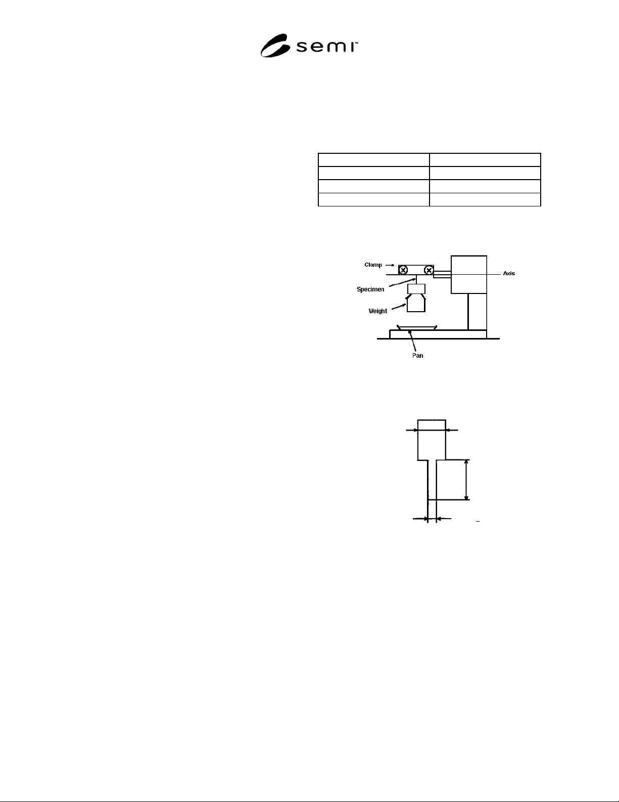
A1-2.1 Equipment — Automatic or manual lead bend
fatigue tester as shown in Figure A1-1.
A1-2.2 Preparation of Specimen — The specimen with
the width of 0.5 mm ± 0.05 mm is made by either
etching or stamping method. A wider portion on one
end is recommended for a good grip as shown in Figure
A1-2.
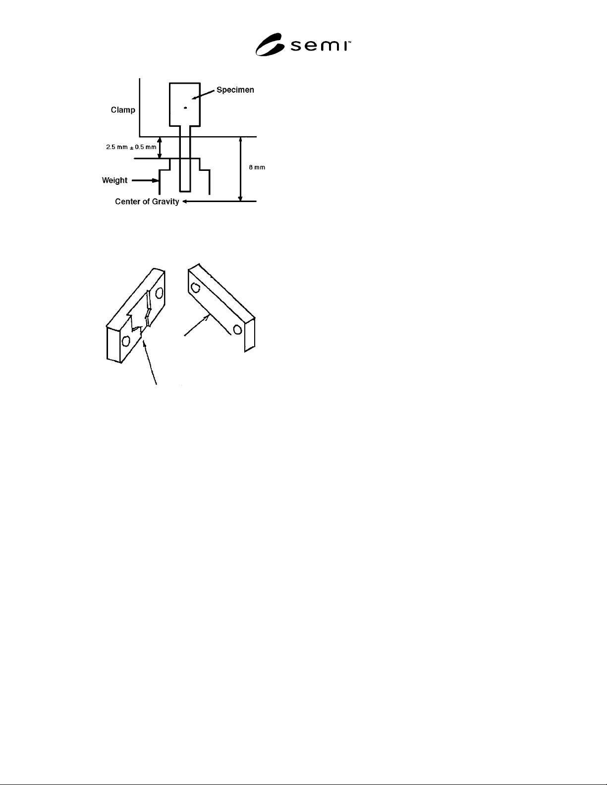
A1-2.3 Procedure — The specimen is clamped on both
ends with clamp and weight as shown in Figure A1-3
and tested under the conditions listed in Table A1-1.
The number of bending cycles (*) and other
information (**) should be recorded.
*The number of bending cycles: The cycles until
specimen breaks, and weight drops into pan.
0° – 90° – 0° bend on one side is counted as 1 cycle.
0° – 90° is counted as 0.5 cycle.
**Other information:
1. Rolling direction on the specimen.
2. Actually measured dimensional data of thickness
and width.
3. Burr side related to bending corner (for stamped
specimen only).
A1-3 Reference
SEMI G10 — Standard Method for Mechanical
Measurement of Plastic Package Leadframes
Table A1-1
Bend Angle (set) 90° ± 2°
Rate of Cycle 2–5 sec/cycle
Weight 2.206–2.452N (225–250 gf)
Bend Radius: R (see Fig. A4) 0.15–0.20 mm
Note 1: In other cross sectional areas (thickness and width) of
leads, the weight to be used shall be agreed upon between
supplier and purchaser.
Figure A1-1
Lead Bend Fatigue Tester
1.5 mm *
Arbitrary
0.5 mm +
0.05 mm
*Wide tip to reduce slipping
—
Figure A1-2
Shape of Specimen
SEMI G4-0302 © SEMI 1982, 2002 9
Figure A1-3
Clamping
Back
Front
R = 0.15 - 0.2 mm
Fitted grooves to reduce slipping
Figure A1-4
Inside of Clamp (Example)