semi合集-English.pdf - 第47页
SEMI E2.2-93 © SEMI 1988, 2003 1 SEMI E2.2-93 (Withdrawn 1103) STANDARD FOR 200 mm QUARTZ AND HIGH TEMPERATURE WAFER CARRIERS This standard was techn ically reapproved b y the Ph ysical Interfaces & Carriers Committe…
SEMI E2-93 © SEMI 1986, 2003 4
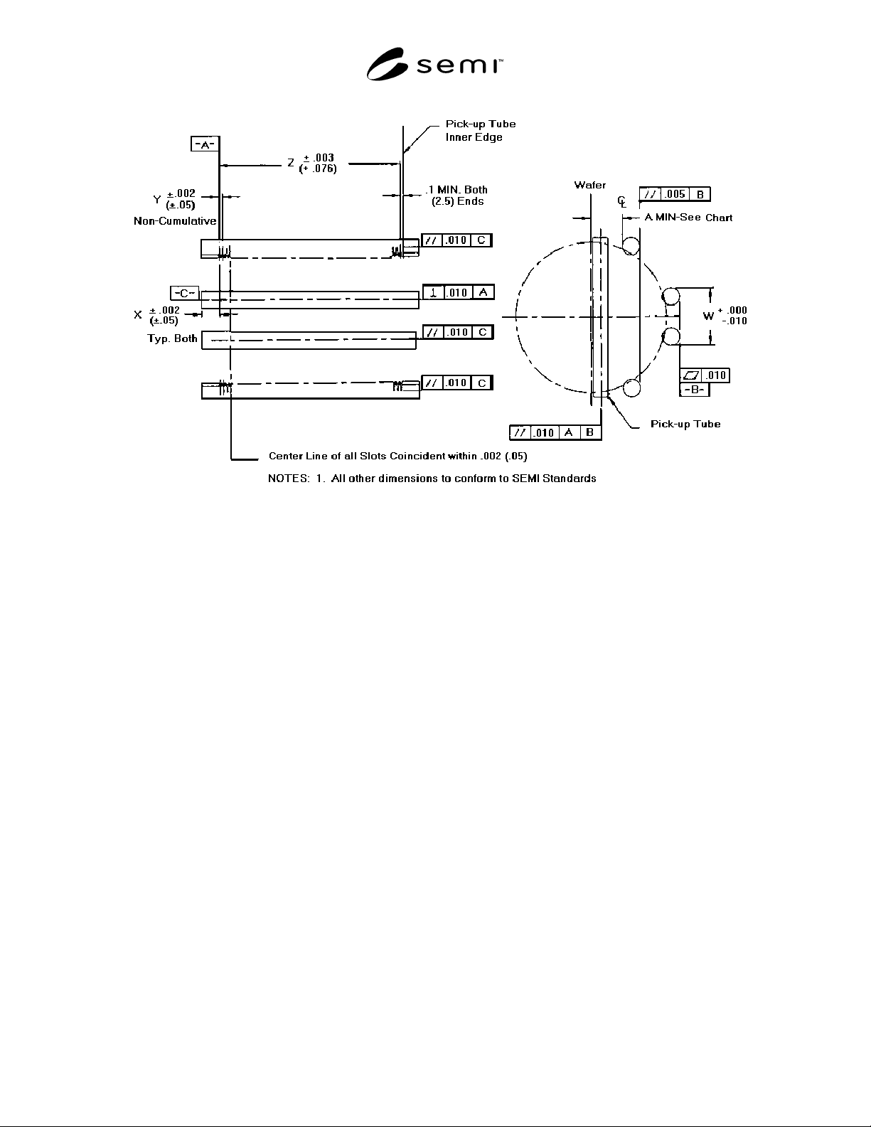
Figure A1-2
Style 2: Contiguous
NOTICE: These standards do not purport to address safety issues, if any, associated with their use. It is the
responsibility of the user of these standards to establish appropriate safety and health practices and determine the
applicability of regulatory limitations prior to use. SEMI makes no warranties or representations as to the suitability
of the standards set forth herein for any particular application. The determination of the suitability of the standard is
solely the responsibility of the user. Users are cautioned to refer to manufacturer' s instructions, product labels,
product data sheets, and other relevant literature respecting any materials mentioned herein. These standards are
subject to change without notice.
The user' s attention is called to the possibility that compliance with this standard may require use of copyrighted
material or of an invention covered by patent rights. By publication of this standard, SEMI takes no position
respecting the validity of any patent rights or copyrights asserted in connection with any item mentioned in this
standard. Users of this standard are expressly advised that determination of any such patent rights or copyrights, and
the risk of infringement of such rights, are entirely their own responsibility.
Copyright by SEMI® (Semiconductor Equipment and Materials
International), 3081 Zanker Road, San Jose, CA 95134. Reproduction o
f
the contents in whole or in part is forbidden without express written
consent of SEMI.
SEMI E2.2-93 © SEMI 1988, 2003 1
SEMI E2.2-93 (Withdrawn 1103)
STANDARD FOR 200 mm QUARTZ AND HIGH TEMPERATURE
WAFER CARRIERS
This standard was technically reapproved by the Physical Interfaces & Carriers Committee and is the direct
responsibility of the North American Physical Interfaces & Carriers Committee. Current edition approved by
the North American Regional Standards Committee in October 1998. Initially available at www.semi.org
February 1999; to be published February 1999. Originally published in 1988; previous published revision in
1996.
NOTICE: This document was balloted and approved for withdrawal in 2003.
NOTE: Terms and Dimensions used in this specification are defined in SEMI E2.
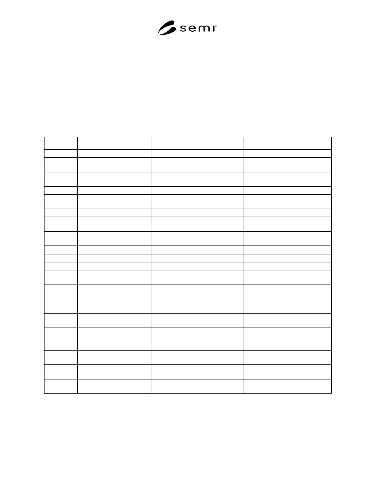
Description Style 1 — Non-Contiguous (Figure 1) Style 2 — Contiguous (Figure 2)
Symbol
A Wafer Height 105.6 mm REF
(4.14 in. REF)
105.6 mm REF
(4.14 in. REF)
B Base Width 66.040 mm ± 0.508 mm
(2.600 in. ± 0.020 in.)
66.040 mm ± 0.508 mm
(2.600 in. ± 0.020 in.)
D Lift Access Height 17.8 mm (0.70 in.) 17.8 mm (0.70 in.)
E Lift Access Spacing 178.562 mm ± 0.760 mm
(7.030 in. ± 0.030 in.)
154.940 mm ± 0.760 mm
(6.100 in. ± 0.030 in.)
F Lift Access Opening 6.0 mm (0.236 in.) min. same
J Pocket Size (DIA) 202 mm ± 0.500 mm
(7.953 in. ± 0.020 in.)
202 mm ± 0.500 mm
(7.953 in. ± 0.020 in.)
K Base Side to Wafer Centerline 33.02 mm ± 0.254 mm
(1.300 in. ± 0.010 in.)
1/2 B ± 0.254 mm
(1.300 in. ± 0.010 in.)
L Carrier Region
150° max. 125° max.
P Separation — Wafer to Wafer ≥ 10% H ≥ 10% H
25 Capacity
C Base Length C = 195.15 mm ± 0.076 mm
(7.683 in. ± 0.003 in.)
157.750 mm ± 0.076 mm
(6.250 in. ± 0.003 in.)
G Base End to 1st Slot G = 21.374 mm ± 0.076 mm
(0.8415 ± 0.003 in.)
3.175 mm ± 0.076 mm
(0.125 in. ± 0.003 in.)
H Slot Spacing
(non-accumulative)
6.350 mm ± 0.076 mm
(0.250 in. ± 0.003 in.)
6.350 mm ± 0.076 mm
(0.250 in. ± 0.003 in.)
I End Slot to End Slot 152.400 mm ± + 0.076 mm
(6.000 in. ± 0.003 in.)
152.400 mm ± + 0.076 mm
(6.000 in. ± 0.003 in.)
50 Capacity
C Base Length 195.148 mm ± 0.076 mm
(7.683 in. ± 0.003 in.)
158.750 mm ± 0.076 mm
(6.260 in. ± 0.003 in.)
G Base End to 1st Slot 19.787 mm ± 0.076 mm
(0.779 in. ± 0.003 in.)
3.175 mm ± 0.076 mm
(0.125 in. ± 0.003 in.)
H Slot Spacing
(non-accumulative)
3.18 mm ± 0.08 mm
(0.125 in. ± 0.003 in.)
3.18 mm ± 0.08 mm
(0.125 in. ± 0.003 in.)
I End Slot to End Slot 155.575 mm ± 0.076 mm
(6.125 in. ± 0.003 in.)
155.575 mm ± 0.076 mm
(6.125 in. ± 0.003 in.)

SEMI E2.2-93 © SEMI 1988, 2003 2
NOTICE: These standards do not purport to address safety issues, if any, associated with their use. It is the
responsibility of the user of these standards to establish appropriate safety and health practices and determine the
applicability of regulatory limitations prior to use. SEMI makes no warranties or representations as to the suitability
of the standards set forth herein for any particular application. The determination of the suitability of the standard is
solely the responsibility of the user. Users are cautioned to refer to manufacturer's instructions, product labels,
product data sheets, and other relevant literature respecting any materials mentioned herein. These standards are
subject to change without notice.
The user's attention is called to the possibility that compliance with this standard may require use of copyrighted
material or of an invention covered by patent rights. By publication of this standard, SEMI takes no position
respecting the validity of any patent rights or copyrights asserted in connection with any item mentioned in this
standard. Users of this standard are expressly advised that determination of any such patent rights or copyrights, and
the risk of infringement of such rights, are entirely their own responsibility.
Copyright by SEMI® (Semiconductor Equipment and Materials
International), 3081 Zanker Road, San Jose, CA 95134. Reproduction o
f
the contents in whole or in part is forbidden without express written
consent of SEMI.