semi合集-English.pdf - 第4290页
SEMI F81-1103 © SEMI 2003 5 8.2 Exam ples of acceptable tools, magnification, and illumination includ e, but are not limited to , the following: 8.2.1 Tools — sight pipe; rigid borescope; cal ipers; v- blocks; di al indi…

SEMI F81-1103 © SEMI 2003 4
5.1.61 welder — a person who does welding
(sometimes used to refer to a welding machine or
power supply).
5.1.62 welding equipment — power supply, weld
heads, torches, and associated cables and accessories
used for welding.
5.1.63 welding operator — a person who welds with
an orbital or machine welding system.
6 Ordering Information
6.1 The purchase order for services to be supplied in
compliance with this specification shall include the
following information:
6.1.1 Purchase order number
6.1.2 Reference to applicable specifications
6.1.3 Documentation and certification requirements
6.1.3.1 Disposition of documentation and coupons
6.1.3.2 Disposition of nonconforming product
6.1.4 Inspection methods and tools
6.1.4.1 Qualifications for inspector/examiner; for
example, ASNT SNT-TC-1A or AWS QC-1
6.1.4.2 % level inspection for quality assurance or
quality control
7 Requirements
7.1 Welds shall be produced in conformance with the
procedures and requirements outlined in SEMI F78
“Practice for Gas Tungsten Arc (GTA) Welding of
Fluid Distribution Systems in Semiconductor
Manufacturing Applications.” All weld beads shall
conform to the following specifications:
7.1.1 All welds shall exhibit complete penetration
around the entire internal surface. Penetration and bead
width shall be uniform throughout the entire weld.
7.1.2 Welds shall have no visible surface cracks,
porosity or inclusions under magnification. (Refer to
Section 8.1 of this standard.) See also Section 7.1.9.
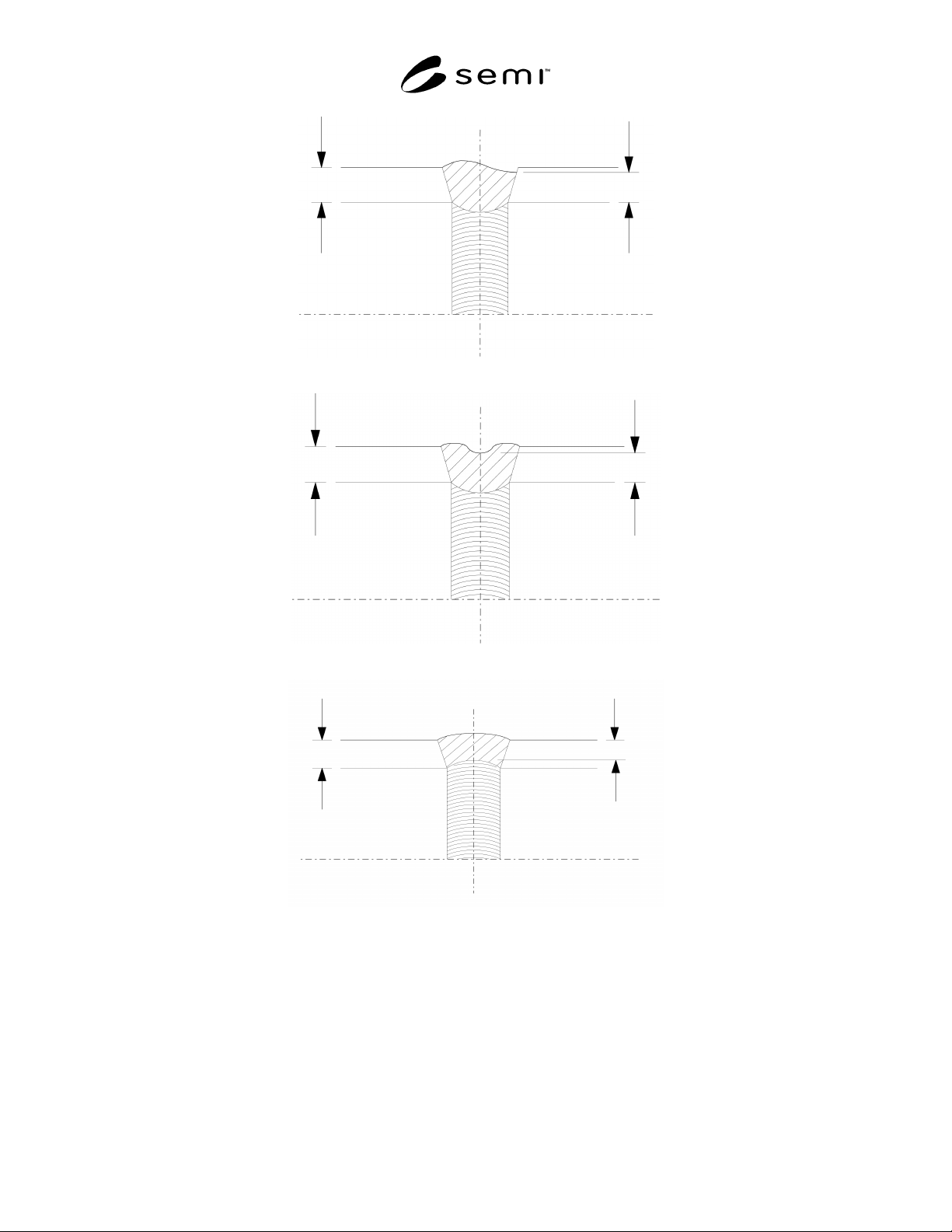
7.1.3 No profile defect reducing the minimum wall
thickness T
min
below that of the parent metal is
permitted at any point in the weld (Figure 1). Undercut
and centerline shrinkage shall not be accepted. ID
concavity is not permitted.
7.1.4 Outer diameter (OD) concavity shall not exceed
10% of the nominal tube wall thickness T on tubing 1
in. (25 mm) and larger. No OD concavity is allowed on
tubing under 1 in. (25 mm) OD convexity shall not
exceed 10% of the nominal wall thickness T (Figure 2).
7.1.5 Inner diameter (ID) convexity shall not exceed
10% of the nominal wall thickness T (Figure 3).
7.1.6 Minimum ID weld bead width shall be 1.0 times
the nominal wall thickness T. Maximum ID bead width
shall be 2.5 times the nominal wall thickness T.
7.1.7 In any individual weld, maximum ID bead width
shall not exceed 1.25 times the minimum bead width
(Figure 4).
7.1.8 ID and OD weld bead meander shall not exceed
35% of the nominal wall thickness T (Figure 5).
7.1.9 The ID weld root surface shall have no porosity,
inclusions or slag when viewed without magnification.
A small slag inclusion at the end of the downslope, with
a diameter less that 10% of the nominal wall thickness
T, that does not affect weld integrity may be acceptable.
7.1.10 The OD weld face width shall be a minimum of
two (2) times the nominal wall thickness T.
7.1.11 Weld bead overlap (the percentage of the first
weld pulse that is covered by the subsequent weld
pulse) shall be at a minimum 80% on the OD and 70%
on the ID along the complete length except the
downslope (Figure 6).
7.1.12 Tack welds must be totally consumed and
undetectable in or around the OD or ID weld bead
(Figure 7).
7.1.13 The OD weld face shall be free of oxidation
except a light straw color is permissible. Light external
oxidation may be removed with a stainless steel wire
brush immediately after welding unless prohibited by
the end user.
7.1.14 There shall be no visible discoloration on the
tube ID or weld ID when viewed under a bright
fluorescent light without magnification (HP and UHP
systems only). Above 2 in. (50 mm) in diameter, a
slight blue color may be acceptable.
7.1.15 Axial misalignment shall not exceed 10% of the
nominal wall thickness T (Figure 8).
7.1.16 Angular misalignment shall not exceed ± ½
degree (1/8 in. per foot or 10 mm per m) (Figure 9).
7.1.17 The weld downslope must be present and of
sufficient length to prevent a crater at the end of the
weld. The distance between the ID downslope and the
OD downslope shall be a minimum of 3 times the
nominal wall thickness T (Figure 10).
8 Inspection Tools and Methods
8.1 Acceptable tools, magnification, and illumination
shall be specified and agreed upon between the supplier
and purchaser, per Section 6.1.4 of this document.

SEMI F81-1103 © SEMI 2003 5
8.2 Examples of acceptable tools, magnification, and
illumination include, but are not limited to, the
following:
8.2.1 Tools — sight pipe; rigid borescope; calipers; v-
blocks; dial indicators; comparators
8.2.2 Magnification — magnifying glass; optical
microscope (2 to 40×)
8.2.3 Illumination — flashlight; bright fluorescent
light; natural (ambient) light; white paper (for
background illumination)
8.3 All tools shall be used without damaging or
contaminating the wetted surface of production
weldments. Tools may touch the wetted surface of
coupons.
9 Certification
9.1 Upon request of the purchaser in the contract or
order, a manufacturer' s or supplier' s certification that
the product was manufactured and tested in accordance
with this specification, together with a report of the test
results, shall be furnished at the time of shipment.
9.2 If desired, the supplier and purchaser may agree
that the product shall be certified as “capable of
meeting” certain requirements. In this context,
“capable of meeting” shall signify that the supplier is
not required to perform the appropriate tests. However,
if the purchaser performs the test(s) and the product
fails to meet the requirement(s), the product may be
subject to rejection.
SEMI F81-1103 © SEMI 2003 6
(a) Undercut
(b) Center line shrinkage
(c) ID concavity
Figure 1
Rejectable Profile Defects