semi合集-English.pdf - 第4683页
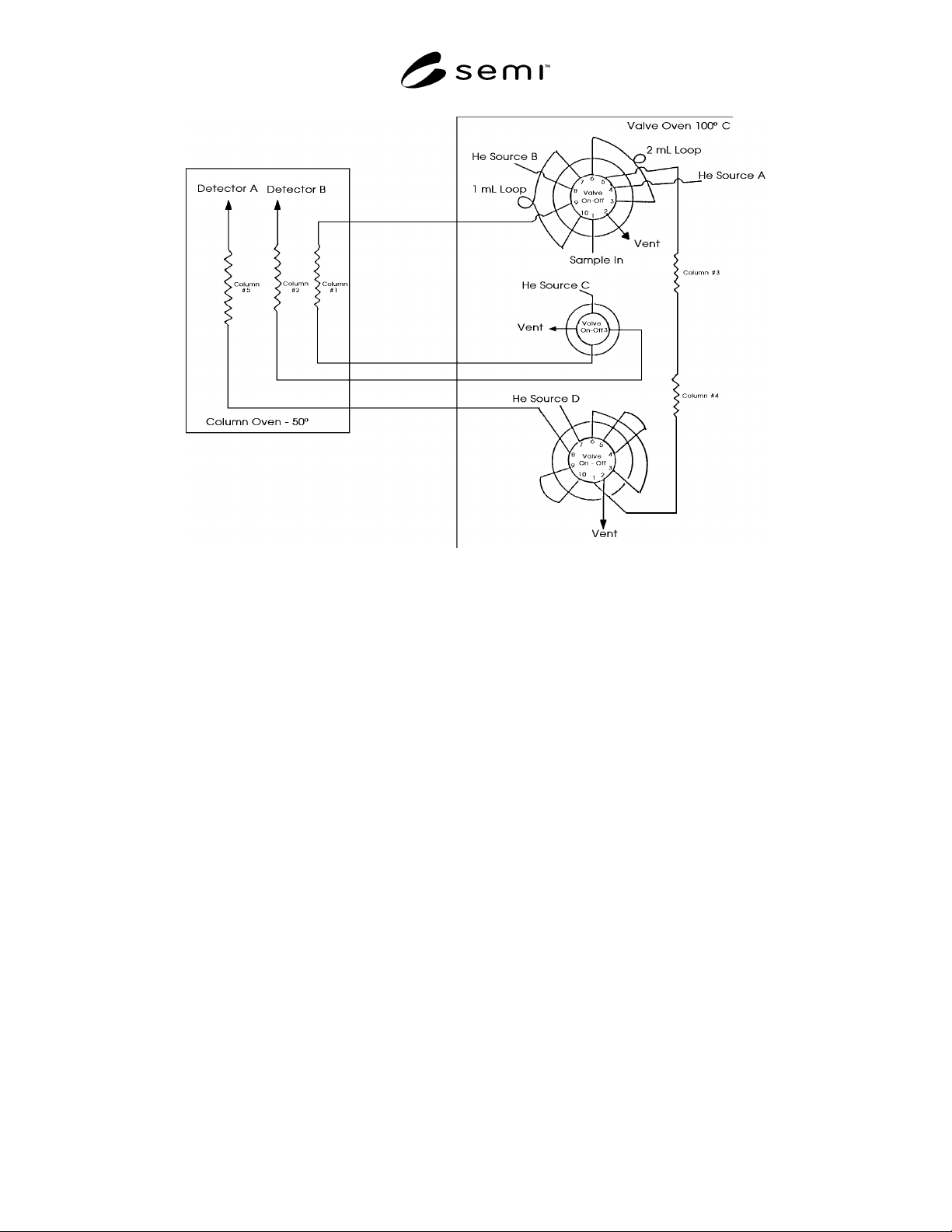
SEMI C3.37-07 01 © SEMI 1989 , 2001 3 Figure 1 Configuration for the Analysis of O 2 , N 2 O 2 in C 2 F 6 NOTICE: T hese st andards do n ot purport to address safety issu e s, if any, associated with their use. It is t h…
SEMI C3.37-0701 © SEMI 1989, 2001 2
minutes, carbon monoxide 14.5 minutes and carbon
dioxide 15.9 minutes.
5.1.4.2 Analyze the hexafluoroethane sample to be
tested in the same manner as in 5.1.4.1
5.1.4.3 Repeat 5.1.4.1.
5.1.4.4 Calculate the concentration of oxygen,
nitrogen, carbon monoxide and carbon dioxide in the
sample, using the formula below. The result may not
exceed specification in Section 2 of this Standard.
Sample Pea
k
Are
a
Standard Peak Are
a
×
Concentratio
n
of Standar
d
=
Concentratio
n
of Sam
p
le
5.2 Halogenated Hydrocarbons — This procedure is
for the determination of halogenated hydrocarbons in
hexafluoroethane using a gas chromatograph with a
flame ionization detector.
5.2.1
Detection Limit — 0.5 ppm (mol/mol).
5.2.2 Instrument Parameters
5.2.2.1 Column: 1% SP-1000 on Carbopak B, 60/80
mesh, 7.3 m (24 ft) by 3.2 mm (1/8 in) OD ss, or
equivalent.
5.2.2.2
Carrier Flow: 40 mL/min helium
5.2.2.3 Support Gases: Set the flow rates as specified
by the instrument manufacturer.
5.2.2.4 Sample Volume: 2.0 mL
5.2.2.5 Temperatures:
Detector 250°C
Initial Oven 35°C
Pre-Program Hold 7 min
Temperature Rise 10°C/min
Final Oven 150°C
5.2.3 Calibration Standard — 5 ppm (mol/mol) each
CF
3
H, C
2
F
6
, CF
3
Cl, CF
2
HCl, C
2
F5Cl balance helium.
5.2.4 Operating Procedure
5.2.4.1 Inject a sample of the calibration standard into
the column using a gas sampling valve. Record
retention times and peak areas. The order of elution is
CF
3
H, C
2
F
6
, CF
3
Cl, CF
2
HCl, C
2
F
5
Cl.
5.2.4.2 Analyze the hexafluoroethane sample to be
tested in the same manner as in 5.2.4.1.
5.2.4.3 Repeat 5.2.4.1.
5.2.4.4 Calculate the concentration of each impurity in
the sample using the formula below. Total the amounts
of chlorofluorocarbons and hydrofluorocarbons. The
result may not exceed the specification in Section 2 of
this Standard.
Sample Pea
k
Are
a
Standard Peak Are
a
×
Concentratio
n
of Standar
d
=
Concentratio
n
of Sam
p
le
5.3 Water (See Note 4) — This procedure is for the
determination of trace moisture (water) in
hexafluoroethane, using a continuous flowing
electrolytic hygrometer.
5.3.1
Detection Limit — 1.0 ppm (ppmw). This is
equivalent to a frostpoint of -76°C (-105°F).
5.3.2 Sample Pressure and Flow — Set in accordance
with instrument manufacturer's instructions.
5.3.3
Operation Check — The instrument should be
checked periodically for correct operation. A gas
containing a known amount of moisture should be
passed through the instrument. Agreement between the
hygrometer and the standard should be within their
relative accuracies.
5.3.4
Operating Procedure
5.3.4.1 Obtain a continuous flow sample of the
hexafluoroethane source, using a clean, electropolished
or passivated (see Note 5) stainless steel line which has
been purged dry after exposure to ambient moisture.
5.3.4.2
After purging with a dry gas, allow the sample
gas to flow through the sampling system and
hygrometer until a stable reading is obtained. The
reading may not exceed specification in Section 2 of
this Standard.
5.4
Notes
NOTE 1: Introduce the calibration standard as many times as
necessary to achieve the desired precision.
NOTE 2: All gases used in the analysis of the sample should
not contain more than 10% of the specified value of the
component of interest, unless otherwise stated.
NOTE 3: Samples of hexafluoroethane should be equilibrated
at no less than 22°C (72°F) for at least 24 hours prior to
analysis to ensure that the material, whose critical temperature
is 20°C (68°F), is single phase.
NOTE 4: The sampling system and hygrometer must be
designed to operate at the sample pressure, or the sample
pressure must be reduced (by a regulator with a stainless steel
diaphragm) to accommodate the pressure restrictions of the
hygrometer.
NOTE 5: A passivation procedure is described in Metals
Handbook, Eighth Edition, Volume 2, ASM International,
Metals Park, Ohio.
SEMI C3.37-0701 © SEMI 1989, 20013
Figure 1
Configuration for the Analysis of O
2
, N
2
O
2
in C
2
F
6
NOTICE: These standards do not purport to address safety issues, if any, associated with their use. It is the
responsibility of the user of these standards to establish appropriate safety and health practices and determine the
applicability of regulatory limitations prior to use. SEMI makes no warranties or representations as to the suitability
of the standards set forth herein for any particular application. The determination of the suitability of the standard is
solely the responsibility of the user. Users are cautioned to refer to manufacturer’s instructions, product labels,
product data sheets, and other relevant literature respecting any materials mentioned herein. These standards are
subject to change without notice.
The user’s attention is called to the possibility that compliance with this standard may require use of copyrighted
material or of an invention covered by patent rights. By publication of this standard, SEMI takes no position
respecting the validity of any patent rights or copyrights asserted in connection with any item mentioned in this
standard. Users of this standard are expressly advised that determination of any such patent rights or copyrights, and
the risk of infringement of such rights, are entirely their own responsibility.
Copyright by SEMI® (Semiconductor Equipment and Materials
International), 3081 Zanker Road, San Jose, CA 95134. Reproduction o
f
the contents in whole or in part is forbidden without express written
consent of SEMI.
SEMI C3.47-1101 © SEMI 1993, 20011
SEMI C3.47-1101
SPECIFICATION FOR HYDROGEN BROMIDE (HBr), 99.98% QUALITY
This specification was technically approved by the Global Gases Committee and is the direct responsibility of
the North American Gases Committee. Current edition approved by the North American Regional Standards
Committee on August 27, 2001. Initially available at www.semi.org September 2001; to be published
November 2001. Originally published in 1993; previously published in 1995.
1 Description
1.1 Hydrogen Bromide is an irritating and corrosive
gas with a sharp, penetrating, suffocating odor. It is
colorless and nonflammable, but fumes in moist air.
2 Specifications
QUALITY: 99.98%, ASSAY (Total Acidity): 98% min
Impurities
Maximum Impurities
Acceptable (ppm)*
Carbon Dioxide (CO
2
)50
Carbon Monoxide (CO) 5
Hydrogen Chloride (HCl) **
Methane (CH
4
)15
Oxygen (O
2
) + Nitrogen (N
2
)50
Water (H
2
O) (v/v) 5
TOTAL LISTED IMPURITIES
(excluding metals)
125
Impurities
Maximum Impurities
Acceptable (ppm)*
Iron (Fe) 1 (by weight, vapor phase)
* An analysis of significant figures has not been considered. The
number of significant figures will be based on analytical accuracy and
the precision of the provided procedure.
** To be analyzed and reported (typically 500 ppm).
3 Physical Constants (for information only)
Metric Units U.S. Units
Molecular Weight 80.92 80.92
Boiling Point at 1 atm -66.7°C -88.1°F
Density of gas at 70°F (21.1°C)
and 1 atm
3.333 g/L 0.208 lb/ft
3
Specific gravity of gas 2.7 2.7
Critical Pressure 85.16 bar 1234.8 psia
Critical Temperature 90°C 193.6°F
4 Analytical Procedures
4.1 Nitrogen, Oxygen, Carbon Monoxide, Methane,
and Carbon Dioxide — This procedure is for the
determination of nitrogen, oxygen + argon, carbon
monoxide, methane, and carbon dioxide using a gas
chromatograph with a discharge ionization detector.
4.1.1 Detection Limits
• N
2
< 10 ppb
• O
2
+ Ar < 20 ppb
• CO < 20 ppb
• CH
4
< 10 ppb
• CO
2
< 10 ppb
4.1.2 Instrument Parameters — All components are
analyzed using two columns and two detectors with a
single injection. (See Figure 1.)
4.1.2.1 Columns:
• HayeSep Db 2.0 m (6 ft.) by 3.2 mm (1/8") O.D.
by 2.2 mm (0.085") I.D.
• Molecular Sieve 5A 2.0 m (6 ft) by 3.2 mm (1/8")
O.D by 2.2 mm (0.085") I.D. ss or equivalent
(60/80 mesh)
4.1.2.2 Carrier Flow — 40 mL/min He
4.1.2.3 Sample Volume — 1.0 mL
4.1.2.4 Temperatures:
Detector 100°C
Column 1 40°C
Column 2 100°C
4.1.3 Calibration Standards — 5 ppm of each com-
pound of interest including nitrogen, oxygen, carbon
monoxide, methane, and carbon dioxide in helium.
4.1.4 Operating Procedures
4.1.4.1 Inject a sample of the calibration standard into
the HayeSep column using a gas sample valve. Allow
the effluent of HayeSep column to enter the Molecular
Sieve column until after CO has eluted. Switch the
switching valve to allow the methane and CO
2
to elute
directly into detector A while oxygen, nitrogen, and CO
separate on the molecular sieve column and elute into
detector B. Record retention times and peak areas for
all peaks. The order of elution from the HayeSep
column to detector A is methane and CO
2
. The order of
elution on the molecular sieve column to detector B is
oxygen, nitrogen, and CO.