semi合集-English.pdf - 第4119页
SEMI F61-0301 © SEMI 2001 4 be configu red in a double-pass arra ngement cons isti ng of tw o RO membrane unit s in series. Permeate (filtered w ater) from the first RO unit is sent to the second RO unit to b e filtered …

SEMI F61-0301 © SEMI 20013
4.2.39 UPW (ultra pure water) the highest purity
water produced by a semiconductor water treatment
system, which is sent to the end users for use in
manufacturing.
5 General Requirements
5.1 Materials
Components of the UPW system
must be appropriate to the application and conform to
electrical, mechanical, and purity requirements, as well
as the corrosive properties of the UPW chemistry.
These requirements are defined by the physical
installation environment, local and national code
interpretations, process requirements, and delivery
specifications.
5.2 System Installation The UPW system is
installed according to a protocol that ensures
mechanical integrity, leakproof operation, and no or
minimal contamination being added from distribution
throughout the system.
5.3 Acceptance Tests Acceptance tests are
conducted on each subsystem or system produced. Such
tests may include performance demonstrations,
demonstrations of reliability criteria, and achievement
of purity standards. Such tests are the basis for
acceptance or rejection by the purchaser against a pre-
negotiated set of criteria for the performance of the
system.
5.4 Qualification Testing Qualification testing may
include tests for resistivity, temperature, pressure, TOC,
dissolved oxygen, particle levels, bacteria, total silica,
dissolved silica, non-volatile residue, ions, and metals.
5.5 Monitoring UPW systems are monitored for
continuing performance against desired and achievable
levels of quality. Action limits are generally set to
determine when system performance suggests that
corrective action is required.
5.6 UPW specifications UPW systems are generally
guaranteed to deliver a certain quality of water on an
ongoing basis. The guaranteed performance is
established in advance between the UPW equipment
manufacturer and the system owner. Both qualification
testing and monitoring testing use the guaranteed
specifications to determine the parameters and levels of
purity to be tested.
5.7 Recycle/Reclaim Opportunitie s
There can be
several opportunities for using water within a UPW
system, and should be recognized during the design
phase when possible. Examples are; use of 1
st
pass
reject for cooling tower make-up water, returning UF
reject to Primary or Feed water Tank, re-use of last
stage rinse waters as UPW for lower grade use areas,
i.e., CMP, isolation of CMP waste stream, for possible
reclaim/reuse.
6 Source Water
6.1 Raw Water
is the raw material from which
UPW is made. Untreated raw water is natural water
that is obtained from a surface source such as a lake or
river, or from a ground water source. The raw water to
a UPW system is most frequently treated Municipal
Drinking Water.
6.2 Municipal Drinking Water Most natural raw
waters must be treated in order to produce drinking
water that meets federal and state requirements. There
are upper limits for inorganic contaminants (e.g.,
asbestos, arsenic, copper, and lead), pesticides, volatile
organic chemicals (e.g., benzene, trichloroethylene,
toluene, and xylene), turbidity, microbiological
contaminants, and radiological contaminants (e.g.,
radon 226, radon 228, tritium, and strontium 90).
Municipal Water Treatment may utilize only
chlorination, or filtration and chlorination for certain
ground water sources. For many surface water sources,
coagulation (injection of aluminum or iron salts),
flocculation (injection of a long-chain polymer),
sedimentation, lime or lime/soda ash softening,
filtration, chlorination or chloramination (chlorine plus
ammonia) and other steps may be required.
7 Major Treatment Processe s
7.1 Pretreatment includes all of the water treatment
steps ahead of the Reverse Osmosis Membrane
Treatment step. These steps are primarily required to
protect the membrane units from scaling with sparingly
soluble salts, fouling with living or non-living
suspended particles, or chemical attack by pH,
oxidizing agents or other dissolved contaminants.
Pretreatment equipment may include media filtration,
micro filtration, or ultrafiltration (bulk suspended solids
removal), 1–5 micron cartridge filtration (polishing step
for suspended solids removal), sodium-cycle cation
exchange (softening, to remove scale-forming cations),
acid injection (to minimize cellulose acetate membrane
damage and/or to control carbonate scales), scale
inhibitor injection (to control scaling), activated carbon
filtration (to remove oxidizing agents and certain
organic molecules), and sulfite ion injection (to remove
oxidizing agents).
7.2 Reverse osmosis Membrane Treatment provides
extremely high rejection of dissolved ions (charged
atoms and molecules), organic (carbon containing)
compounds, silica (silicon containing) compounds, and
virtually complete rejection of suspended contaminants,
but will not reject dissolved gases and volatile organic
compounds as well. Reverse osmosis (RO) units may

SEMI F61-0301 © SEMI 2001 4
be configured in a double-pass arrangement consisting
of two RO membrane units in series. Permeate
(filtered water) from the first RO unit is sent to the
second RO unit to be filtered again. It is not
uncommon for the permeate from a double-pass RO
unit to have a resistivity reading up to 0.5–4 Megohm-
cm, with less than one milligram per liter of organic
and silica contaminants. The more contaminants
removed in the membrane treatment step, the lower the
loading on the Polishing steps.
7.3 Volatiles Removal The removal of dissolved
oxygen, carbon dioxide, other gases, and volatile
organic compounds is a necessary treatment step. The
removal of these volatile contaminants is accomplished
to acceptable levels in vacuum degasifiers and in
membrane degasification units. The removal of
volatiles that can form ions and the removal of volatile
organic compounds reduce the loading on downstream
Polishing equipment.
7.4 Polishing The relatively low level of
contaminants that were not removed in the Membrane
Treatment and Volatiles Removal steps are polished
down to acceptable levels in the Polishing steps. Ionic,
organic, and silica contaminants are removed in
typically two stages of Ion Exchange in series (primary
beds and polishing beds). Organic compounds,
measured as TOC (Total Organic Carbon, or Total
Oxidizable Carbon), that are found downstream of the
RO membrane units may be subjected to TOC
Reduction ultraviolet (UV) irradiation (185 nanometer
low pressure units or medium pressure units) to convert
most of them into ionic compounds that can be
effectively removed by Primary Ion Exchange Units
(usually consisting of Separate Beds, Mixed Beds or
EDI/CDI/E-Cell). TOC compounds that exit the
primary ion exchange units are typically subjected to
TOC reducing UV irradiation to break them into
ionized compounds to be removed by the Polishing Ion
Exchange Units. The vast majority of all living
suspended particles (mainly bacteria) that enter any 254
nm UV unit are inactivated. Downstream filters with a
pore size of less than or equal to 0.45 micron remove
the inactivated bacterial bodies. The final filter prior to
Distribution typically has a pore size of less than 0.2
micron.
8 Distribution
8.1 Distribution is frequently comp osed of one or
more Loops. Each loop consists of UPW that
continuously recirculates through appropriate piping
from the final filters, to the manufacturing areas
requiring UPW (end users), and back to a tank located
within the Polishing section to be polished again. The
UPW to the end-user area is commonly called the
Supply. The UPW that travels from the end-user area
back to the water treatment area is commonly called the
Return. Ozone may be injected into the Supply and/or
Return line to control microbiological contaminants and
also to enhance the action of TOC breakdown in
downstream TOC reducing UV units. Sometimes ozone
is injected into the Supply line for similar reasons
(requires de-ozonation at the end-use points).
Sometimes the UPW in the distribution loop is heated
(hot loop) for particular processes.
8.2 Basic System Components
8.3 General Each UPW system contains certain
basic components and a variety of design options to
meet particular customer and facility needs. An
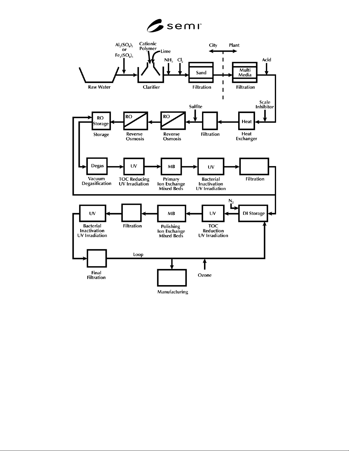
example of a UPW system is shown in Figure 1
attached.
9 Related Documents
9.1 SEMI Standards
SEMI F4 — Guide for Standard Performance,
Practices, and Sub-Assembly for High Purity Piping
Systems and Final Assembly for Semiconductor
Manufacturing Equipment
SEMI F31 — Guide for Bulk Chemical Distribution
Systems
SEMI S2 — Environmental, Health, and Safety
Guideline for Semiconductor Manufacturing Equipment
9.2 SIA
1
National Technology Roadmap For Process Chemicals
1 Semiconductor Industry Association, 181 Metro Drive, Ste 150, San
Jose, CA 95110, USA
SEMI F61-0301 © SEMI 20015
Feed
Water
≤
≤
≤
≤ 5
µ
µµ
µ
≤
≤≤
≤ 1
µ
µµ
µ
≤
≤
≤
≤ 1
µ
µµ
µ
≤
≤
≤
≤ 0.02
µ
µµ
µ
Figure 1
Schematic of a Typical Ultrapure Water System
NOTICE: SEMI makes no warranties or representations as to the suitability of the standards set forth herein for any
particular application. The determination of the suitability of the standard is solely the responsibility of the user.
Users are cautioned to refer to manufacturer’s instructions, product labels, product data sheets, and other relevant
literature respecting any materials or equipment mentioned herein. These standards are subject to change without
notice.
The user’s attention is called to the possibility that compliance with this standard may require use of copyrighted
material or of an invention covered by patent rights. By publication of this standard, SEMI takes no position
respecting the validity of any patent rights or copyrights asserted in connection with any item mentioned in this
standard. Users of this standard are expressly advised that determination of any such patent rights or copyrights, and
the risk of infringement of such rights, are entirely their own responsibility.
Copyright by SEMI® (Semiconductor Equipment and Materials
International), 3081 Zanker Road, San Jose, CA 95134. Reproduction o
f
the contents in whole or in part is forbidden without express written
consent of SEMI.