semi合集-English.pdf - 第3641页
SEMI E142-0705 © SEMI 2005 3 7.3.3 Service Message Definition 7.3.3.1 A service message defini tion table de fines the paramete rs used in a service, as s hown in the followi ng table: Parameter Req/Ind Rsp/Cnf Comment 7…
SEMI E142-0705 © SEMI 2005 2
7 Conventions
7.1 Object Conventions — This document conforms to the conventions for objects established by SEMI E39,
including object diagrams, object terminology, and requirements for standardized objects. Accordingly, notation is
based on Unified Modeling Language (UML).
7.2 Object Attribute Representation — The object information models for standardized objects will be supported by
an attribute definition table with the following column headings:
Attribute Name Definition Access Requirement Form
The formal text name of the attribute. Description of the information contained. RO or RW Y or N (see below)
7.2.1 The Access column uses RO (Read Only) or RW (Read and Write) to indicate the access that service-users
have to the attribute.
7.2.2 A ‘Y’ or ‘N’ in the requirement (Rqmt) column indicates if this attribute must be supported in order to meet
fundamental compliance for the service.
7.2.2.1 The Form column is used to indicate the format of the attribute.
7.2.3 Formal Name of an Object — The text capitalizes formal object name references. Similar to the way
capitalization is normally used when discussing entities. When describing something in the general (like cities)
lower case is used, but when a specific entity is of interest (New York City), then first letters are capitalized.
7.2.4 Components of Complex Attributes — The names of object attributes defined in tables are left-justified. The
individual elements of complex attributes are right-justified in order of appearance below the complex attribute.
7.3 Service Message Representation — Services are functions or methods that may be provided by either the
equipment or the host. A service message may be either a request message, which always requires a response, or a
notification message, that does not require a response.
7.3.1 Service Definition
7.3.1.1 A service definition table defines the specific set of messages for a given service resource, as shown in the
following table:
Message Service Name Type Description
7.3.1.2 Type can be either “N” = Notification or “R” = Request & Response.
7.3.1.3 Notification type messages are initiated by the service provider (e.g., the equipment) and the provider does
not expect to get a response from the service user. Request messages are initiated by a service user (e.g., the host).
Request messages ask for data or an activity from the provider. Request messages expect a specific response
message (no presumption on the message content).
7.3.2 Service Parameter Dictionary
7.3.2.1 A service parameter dictionary table defines the description, format and its possible value for parameters
used by services, as shown in the following table:
Parameter Name Description Format: Possible Value
7.3.2.2 A row is provided in the table for each parameter of a service.
SEMI E142-0705 © SEMI 2005 3
7.3.3 Service Message Definition
7.3.3.1 A service message definition table defines the parameters used in a service, as shown in the following table:
Parameter Req/Ind Rsp/Cnf Comment
7.3.3.2 The columns labeled REQ/IND and RSP/CNF link the parameters to the direction of the message. The
message sent by the initiator is called the “Request”. The receiver terms this message the “Indication” or the request.
The receiver may then send a “Response” which the original sender terms the “Confirmation”.
7.3.3.3 The following codes appear in the REQ/IND and RSP/CNF columns and are used in the definition of the
parameters (eg., how each parameter is used in each direction):
M Mandatory Parameter — Must be given a valid value.
C Conditional Parameter — May be defined in some circumstances and undefined in others. Whether a value is given
may be completely optional or may depend on the value of the other parameter.
U User-Defined Parameter.
- The parameter is not used.
= (For response only.) Indicates that the value of this parameter in the response must match that in the primary (if
defined).
8 Overview
8.1 Substrate maps are two dimensional arrays of data that correspond to a physical substrate which may be a wafer,
strip or tray as shown in the Appendices. It is expected that other substrate types will be added to subsequent
releases of this standard.
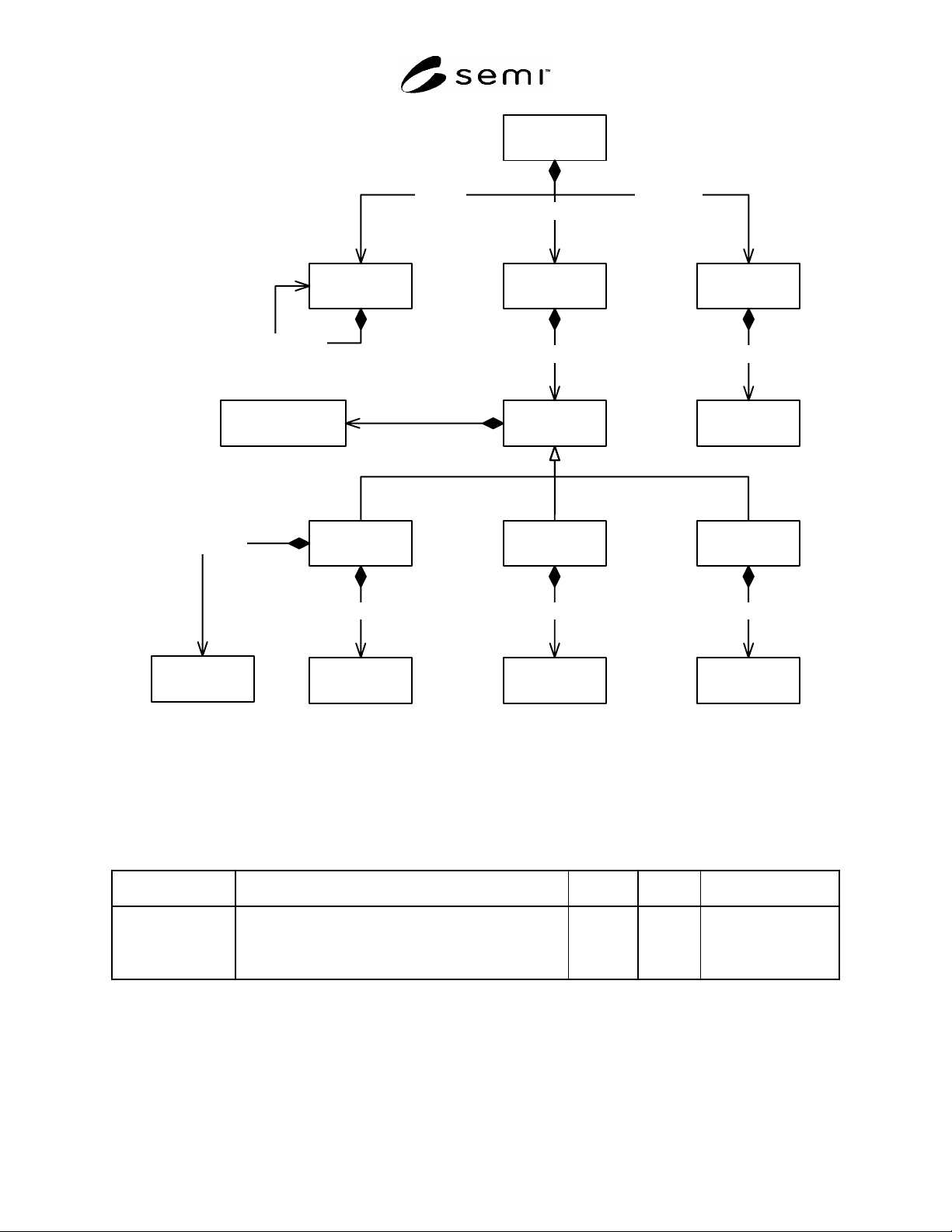
8.2 The data items are defined as attributes of the objects shown in Figure 1 Map Data Object Model.
SEMI E142-0705 © SEMI 2005 4
MapData
BinDefinition
BinCode
DeviceIdMap
Transfer
TransferMap
DeviceId
BinCodeMap
AliasIdOverlayReferenceDevice
SubstrateSubstrateMapLayout
SubstrateMaps
Overlays Aliases
ReferenceDevices
DeviceIds TransfersBinCodes
ChildLayout
BinDefinitions
Layouts Substrates
1
0..*
1..*
1..*
1..*
1..*
0..* 0..*
1
1
1
0..*
0..* 1
11 1
1
0..*
0..*
Figure 1
Map Data Object Model
9 MapData
9.1 The MapData object contains a list of zero or more Layout objects, a list of zero or more SubstrateMap objects
and a list of zero or more Substrate objects.
Table 1 MapData Attributes
Attribute Name Definition Access Reqd Form
FormatRevision Specifies the exact name and revision of the format used
to represent substrate map data. This field can be used by
a parser to automatically determine the format of the
remaining substrate map data.
RO N Text
10 Layout
10.1 The Layout object defines the logical and physical dimensions of two-dimensional array of devices to which a
SubstrateMap may be assigned. A substrate must have a top level layout that defines the size of the substrate itself.
Any layout object can reference other child layout objects. In this way complex assemblies may be represented.
See the examples in Related Information 1.