semi合集-English.pdf - 第6331页
SEMI G65-96 © SEMI 1996, 2004 4 Figure 6 Punch Core Detail
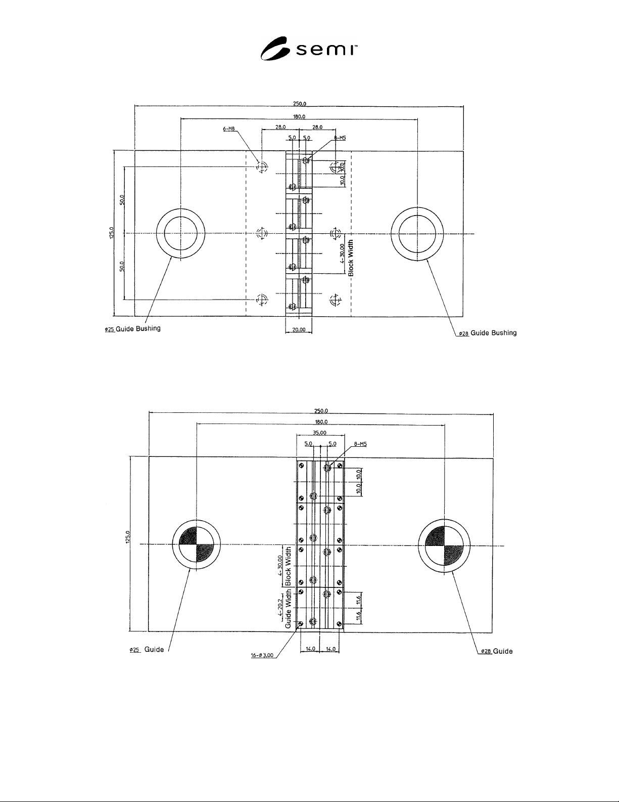
3 SEMI G65-96 © SEMI 1996, 2004
Figure 4
Upper Tool Detail
Figure 5
Lower Tool Detail
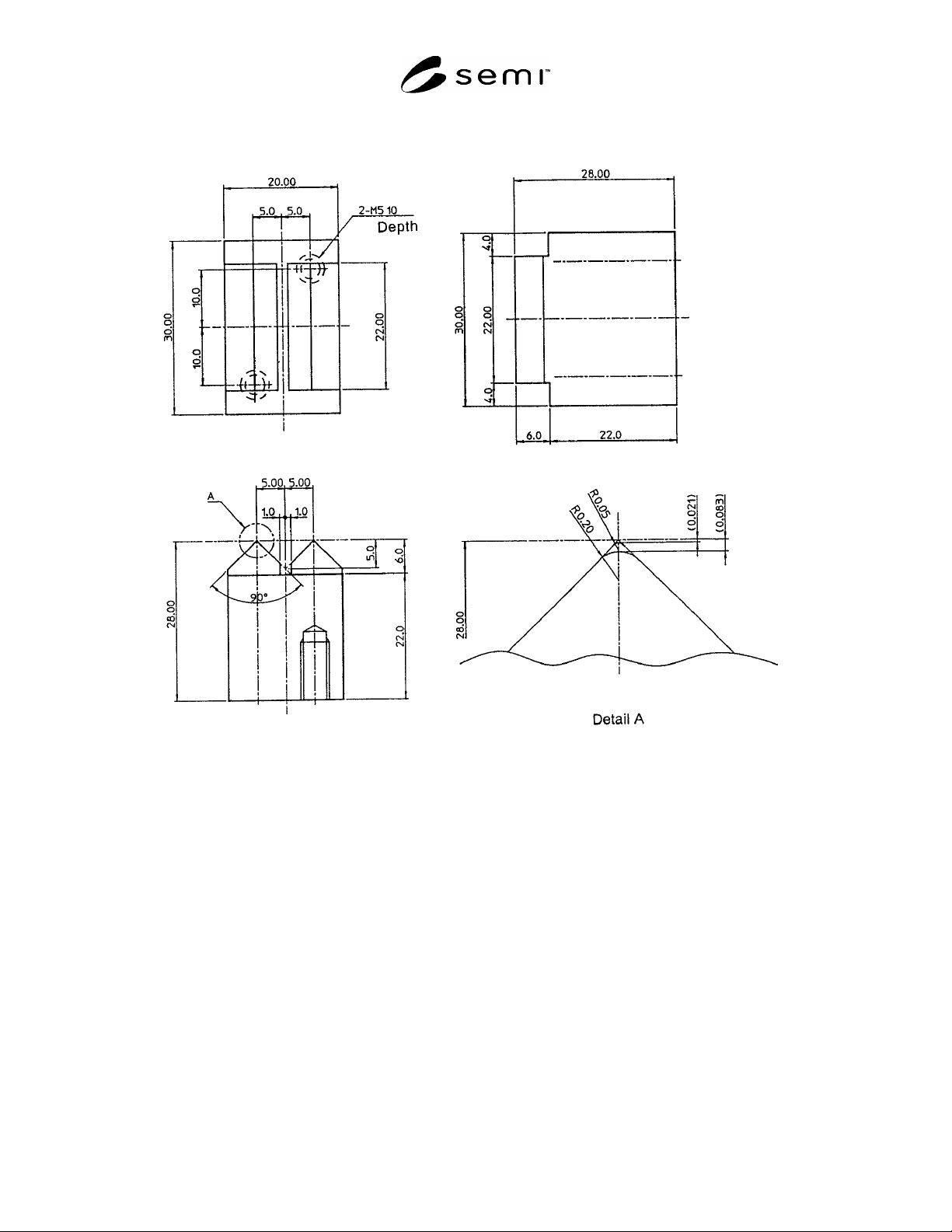
SEMI G65-96 © SEMI 1996, 2004 4
Figure 6
Punch Core Detail
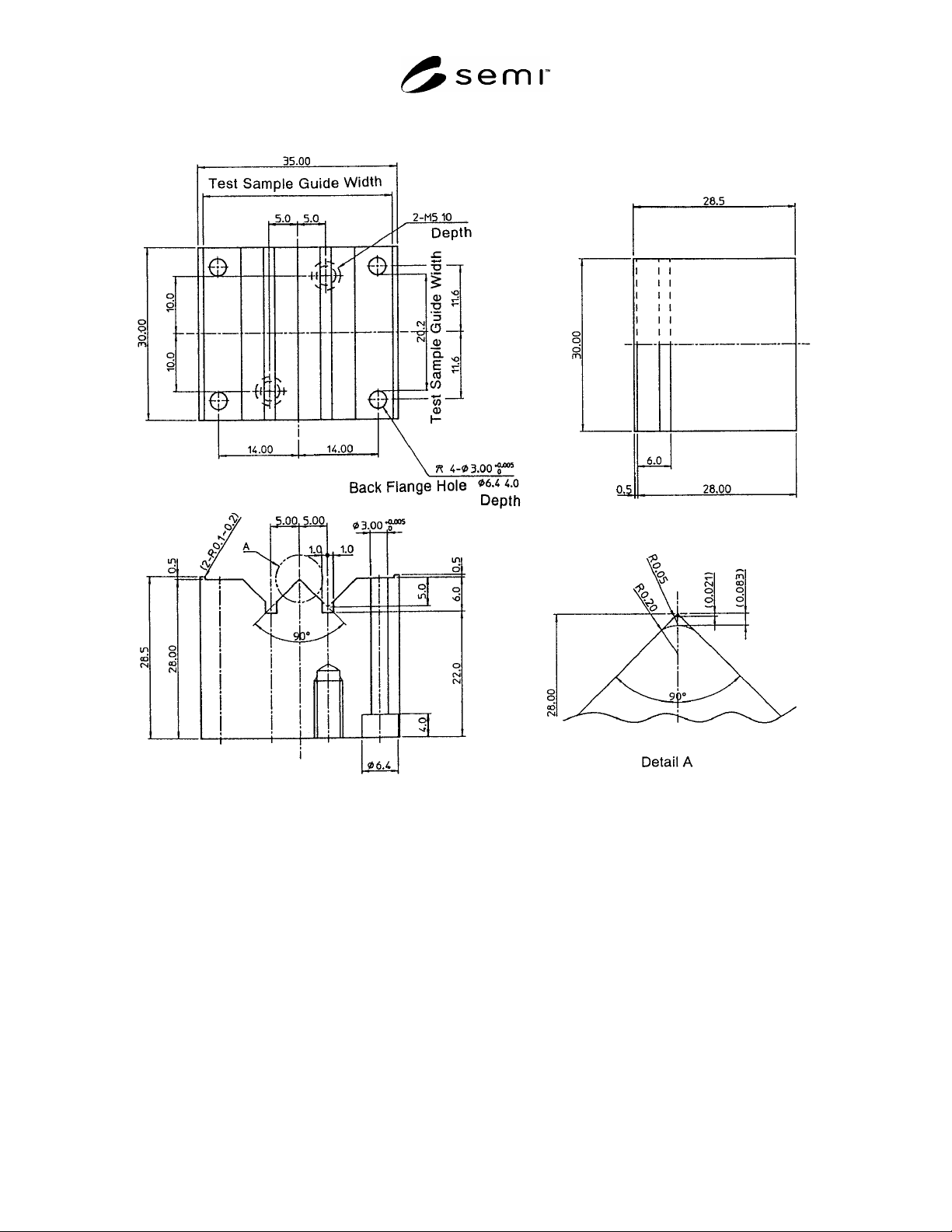
5 SEMI G65-96 © SEMI 1996, 2004
Figure 7
Die Core Detail
8.3 Micrometer
8.4 Microscope — 75× used to inspect lead surface characteristics.
8.5 Protractor — 10× and accuracy 0.1° used to measure the leadform spring back.
8.6 Projector — 10×.
9 Sampling Plan
9.1 The sampling plan shall be agreed between user and supplier. It is suggested that a minimum of five (5) samples
(2 leads per sample) of 0.3 mm width on 0.65 mm pitch, be used for these tests.
NOTE 3: If the leadframe is four-sided, take samples from both orthogonal directions.