semi合集-English.pdf - 第601页
SEMI E83-1000 © SEMI 1999 , 2000 3 RELATED INFORM A TI ON 1 AP P L I C AT I O N N OT E S NOTE: T his related inf or mation is n ot an offic ial part of SEMI E83, but was approve d for p ublicati on by full le tter ballot…
SEMI E83-1000 © SEMI 1999, 2000 2
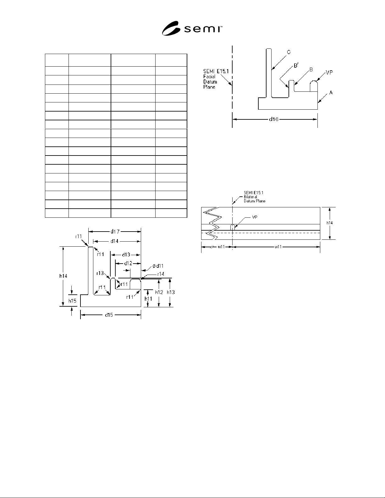
Table 1 Dimensional Requirements
Symbol Value, mm (in.) Tolerance (mm) Type
a11 0 deg. +/- 0.25 deg. angle
∅d11
15.0 (.591) +/- 0.2 diameter
d12 33.0 (1.299) +/- 0.2 distance
d13 39.0 (1.535) +/- 0.2 distance
d14 62.0 (2.441) +/- 0.2 distance
d15 80.0 (3.150) +/- 0.2 distance
d16 237.5 (9.350) +/- 2.5 distance
d17 68.0 (2.677) minimum distance
h11 24.0 (.945) +/- 0.2 distance
h12 39.0 (1.535) +/- 0.2 distance
h13 40.0 (1.575) +/-0.2 distance
h14 83.0 (3.268) +/-0.2 distance
h15 20.0 (.787) maximum distance
r11 2.0 (.079) +/-0.2 radius
r13 4.0 (.157) +/-0.2 radius
r14 5.0 (.197) +/-0.2 radius
w11 200 (7.874) minimum distance
Figure 1
Side Elevation View I
6.3 The flange must be installed such that the vertical
pin (VP) is capable of being aligned with the load port
bilateral datum plane (as defined in SEMI E15.1) and
surface A is a distance of d16 from the load port facial
datum plane (as defined in SEMI E15.1). The angle of
incidence between surface A and the facial datum plane
should be capable of adjustment to a11 listed in Table
1.
6.3.1 The docking flange is to be physically isolated
from the equipment and should be mounted such that
the equipment and equipment load port are protected
from the impact incurred during docking.
Figure 2
Side Elevation View II
6.4 When the flange is removed, no mounting
hardware shall remain protruding from the floor.
6.5 Surfaces A, B, B’ and C shown on Figure 2 must
exist per tolerances listed in Table 1.
Figure 3
Front Elevation View
NOTICE:. SEMI makes no warranties or
representations as to the suitability of the standards set
forth herein for any particular application. The
determination of the suitability of the standard is solely
the responsibility of the user. Users are cautioned to
refer to manufacturer’s instructions, product labels,
product data sheets, and other relevant literature
respecting any materials mentioned herein. These
standards are subject to change without notice.
The user’s attention is called to the possibility that
compliance with this standard may require use of
copyrighted material or of an invention covered by
patent rights. By publication of this standard, SEMI
takes no position respecting the validity of any patent
rights or copyrights asserted in connection with any
item mentioned in this standard. Users of this standard
are expressly advised that determination of any such
patent rights or copyrights, and the risk of infringement
of such rights, are entirely their own responsibility.

SEMI E83-1000 © SEMI 1999, 20003
RELATED INFORMATION 1
APPLICATION NOTES
NOTE: This related information is not an official part of SEMI E83, but was approved for publication by full letter ballot
procedures on July 14, 2000.
R1-1 The intent of this standard is to provide manually
guided 300mm carrier transport PGVs a standard flange
for docking and to facilitate a safe, quick, and
repeatable PGV to load port carrier transfer method or
mechanism. Standardization of features on the flange is
intended to allow for interoperability between PGV
designs and the docking flange.
R1-2 SEMI E64 defines Zone L as an exclusion zone
in SEMI E15.1 compliant tools. It is intended that the
docking flange be mounted in this zone.
R1-3 The docking interface flange includes features to
allow for the following minimum functionality of the
PGV to flange docking procedure:
• Stopping PGV motion
• Guidance of PGV to flange
• x, y & theta alignment of the PGV to the flange
• Locking of PGV to flange
• Docking parallel or perpendicular to the flange
R1-4 The PGV side of the interface may include
additional features to allow for all or some of the
following functionality:
• Compliance to the docking flange
• To dampen impact of docking forces
R1-5 No features on the standard docking flange
provide an adjustable feature to indicate the height
(dimension as H defined by SEMI E15.1) the load port
horizontal datum plane has been adjusted to.
R1-6 It is likely that the alignment error and tolerance
stack up between the docking interface flange and the
equipment load port will not provide sufficient
accuracy alone for accurate pick/placement of a pod
onto the kinematic couplings on the load port.
R1-7 Possible sources of alignment error are:
• Cleanroom floor height and level
• PGV wheels and framework
• Installation accuracy of docking interface flange
• Stability of mounting
R1-8 It may be necessary to use additional alignment
methods to improve accuracy of pod placement onto the
kinematic couplings.
R1-9 It is expected that the interface device be floor
mounted. Thus, the equipment must not require the use
of support pedestals or other support structures under
the floor below Zone L.
R1-10 The docking flange should sustain docking
impact for the lifetime of the flange without any
performance degradation.
• Assume 90kg (200lb) PGV moving at 0.3m/s
(1ft/sec)
• Assume 250,000 docking cycles within a flange
lifetime
• Recommended to design for 3x safety factor for
single docking cycle
R1-11 Flange must be quick remove, replace, align and
calibrate.
R1-12 Surface B' (shown on Figure 2) allows docking
mechanism designs to grab onto the docking flange
without using the docking pin for support.
R1-13 The method of attaching the vertical pin to the
flange is not defined in this standard. Docking flange
designers should be aware of the docking forces
incurred on this pin and design the attachment method
accordingly.
R1-14 The method of attaching the flange to the floor
is not defined in this standard. Docking flange
designers should be aware of the docking forces
incurred on the flange and/or pin and design the
attachment method accordingly.
R1-15 This standard specifies the radii of certain edges
found on the docking flange. It is recommended that
edges that do not have a specified radius are radiused or
broken to eliminate sharp edges.
R1-16 It is left to user to define the needed flange
length (w2×2) at the time of placing an order.
NOTICE:. SEMI makes no warranties or
representations as to the suitability of the standards set
forth herein for any particular application. The
determination of the suitability of the standard is solely
the responsibility of the user. Users are cautioned to
refer to manufacturer’s instructions, product labels,
product data sheets, and other relevant literature

SEMI E83-1000 © SEMI 1999, 2000 4
respecting any materials mentioned herein. These
standards are subject to change without notice.
The user’s attention is called to the possibility that
compliance with this standard may require use of
copyrighted material or of an invention covered by
patent rights. By publication of this standard, SEMI
takes no position respecting the validity of any patent
rights or copyrights asserted in connection with any
item mentioned in this standard. Users of this standard
are expressly advised that determination of any such
patent rights or copyrights, and the risk of infringement
of such rights, are entirely their own responsibility.
Copyright by SEMI® (Semiconductor Equipment and Materials
International), 3081 Zanker Road, San Jose, CA 95134. Reproduction o
f
the contents in whole or in part is forbidden without express written
consent of SEMI.